
Fire pit cover

a technology for fire pits and covers, applied in the field of fire pit covers, can solve the problems of serious hazards in any conditions when partially covering pits, and achieve the effects of reducing weight, reducing cost, and thinning the center plate material

Inactive Publication Date: 2010-11-30
DEPAUL BRIAN WILLIAM
View PDF3 Cites 6 Cited by
  • Summary
  • Abstract
  • Description
  • Claims
  • Application Information

AI Technical Summary

Benefits of technology

[0013]First, as the cover is installed over a fire pit, the centering ring prevents cover movement since such movement in any direction quickly produces an interference fit between the ring and the fire pit sidewall. Additionally, the centering ring reinforces the center plate allowing use of a thinner center plate material. Therefore, the ring insures that the pit remains fully covered during darkness or during winter months, for example, when the pit area could be covered with snow. A partially cover pit is a serious hazard under any conditions. Additionally, the centering ring insures the structural integrity of the cover. At the same time, the cover has a reduced weight to promote cover handling and reduced cost.
[0014]Another advantage is that, as the cover is installed on a fire pit, the only contact between the pit and the cover is between the bottom edge of the rim and the fire pit ledge. Since this ledge typically is made of stone or like ceramic material, minimizing the area of contact inhibits discoloration of the ledge material if moisture, leaves or like material were to become compressively entrapped between the cover and the ledge.
[0015]A still further advantage is that the perforations of said center plate allow a fire in the fire pit to continue to burn when the cover in place. For a next use the fire pit is substantially free of unburnt matter.

Problems solved by technology

First, as the cover is installed over a fire pit, the centering ring prevents cover movement since such movement in any direction quickly produces an interference fit between the ring and the fire pit sidewall.
A partially cover pit is a serious hazard under any conditions.

Method used


Image

  • Fire pit cover
  • Fire pit cover

Examples


Embodiment Construction

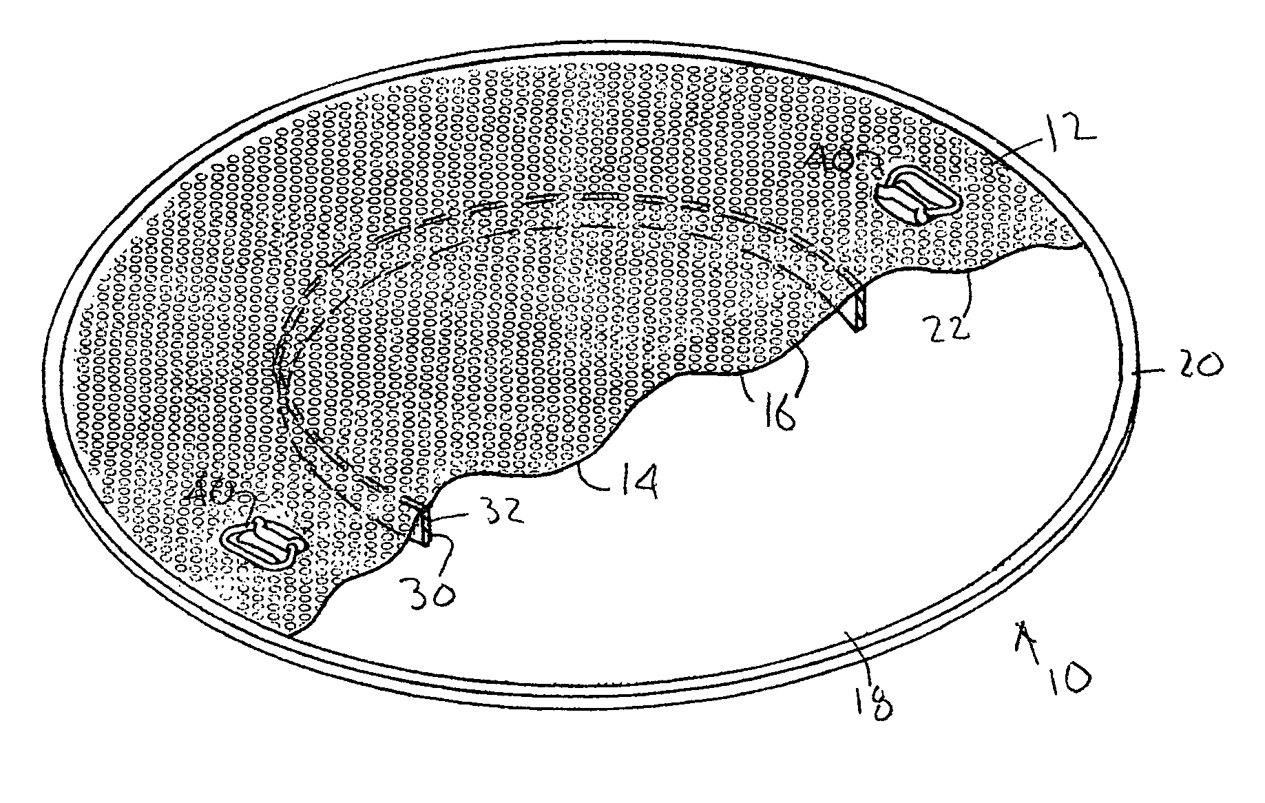
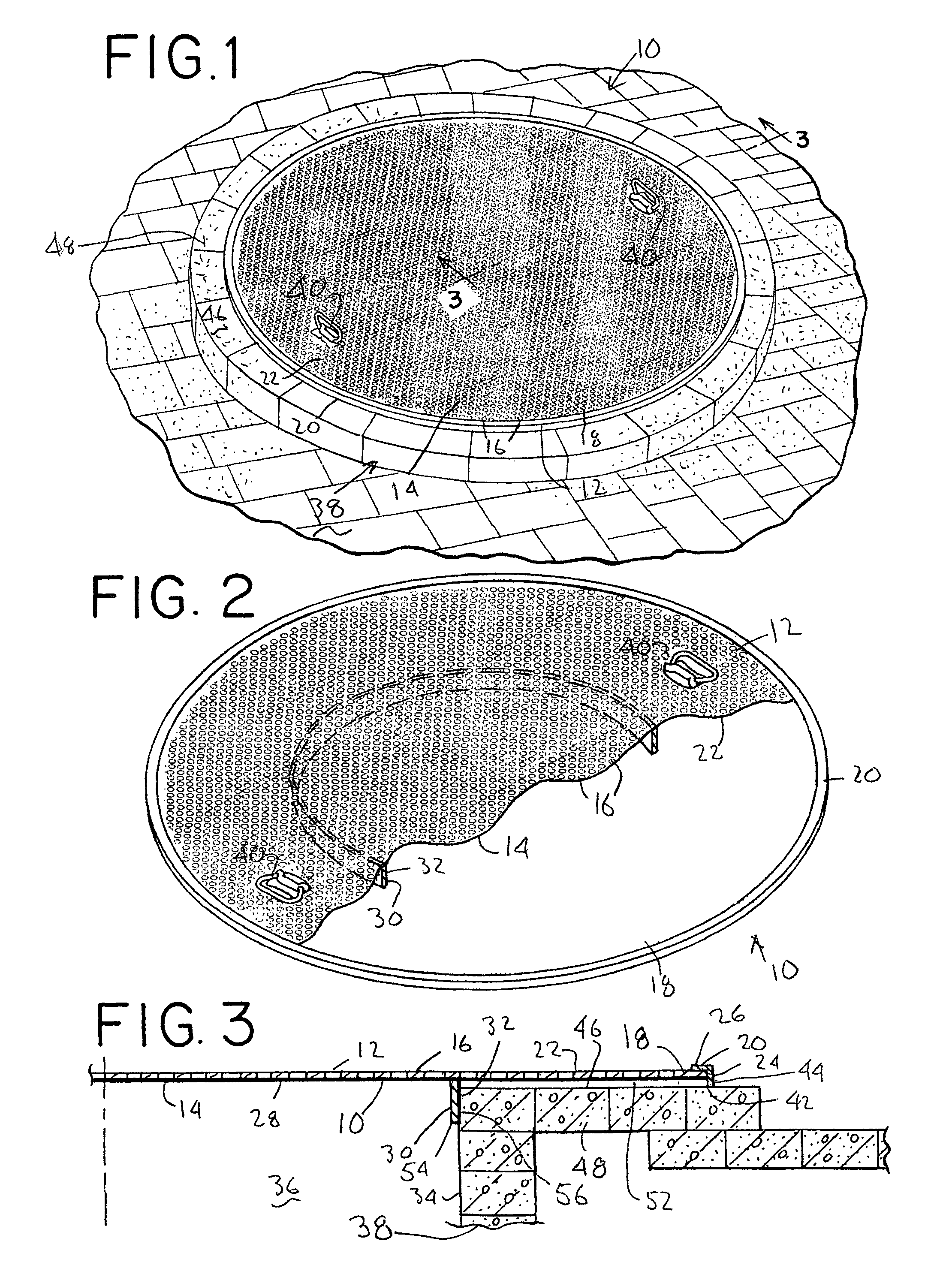
[0019]A fire pit cover of the invention is shown generally in FIGS. 1 and 2 and designated 10. The cover 10 has a circular body 12 comprising a perforated center plate 14. The perforations 16 are spaced and sized so that about 60 percent of the plate 14 is open. As seen in FIG. 3, a peripheral edge 18 of the center plate 14 connects with an angle-shaped rim 20 with a top side 22 of the plate 14 fitting against a bottom surface 24 of a horizontal flange 26 of the rim 20. Attached to a bottom side 28 of the center plate 14 is a centering ring 30. A diameter of an outer side 32 of the ring 30 is sized to fit loosely next to a sidewall 34 of a combustion chamber 36 of a fire pit 38, see FIG. 3. Attached to the top side 22 of the center plate 14 is a pair of spaced apart handle 40. The components of the cover body 12 are preferable made of stainless steel or other like corrosion resistant material.

[0020]When the fire pit 38 is not in use, the cover 10 is placed over the pit 38, see FIG. ...


PUM


Abstract

A cover particularly adapted to extend over outdoor recreational fire pits when not in use includes a circular perforated center plate. Attached to an outer edge of this center plate is an angle-shaped rim having a downward extending vertical flange. Then, attached to a bottom side of the center plate is a centering ring. For use, a pair of spaced apart handles attached to a top side of the center plate may be used to remove the cover so that a fire may be built in the pit and then used to replaced the cover after pit use. In this latter case, the cover is positioned over the pit so that the centering ring extends into the pit next to a vertical sidewall of the pit. Any inadvertent cover movement is inhibited by an interference fit between the cover ring and the pit sidewall.

Description

BACKGROUND OF THE INVENTION[0001]1. Field of the Invention[0002]This invention relates to structure that may selectively fit over further structure containing a fire or heating element and more particularly to a cover that may selectively placed over a circular recreational outdoor fire pit when the pit is not in use.[0003]2. Prior Art[0004]Structures that may be selectively placed over fire holding areas are well known and have been in use for many years.[0005]One early example of such structure is set out in U.S. Pat. No. 5,144 (Talbot) which discloses a Civil War era spider-grate attachable to a set of legs to locate the grate about an open fire. The grate comprises a flat annular ring. Attached to a bottom side of this ring is a set of spaced part inverted U-shaped channel members that provide a flat top surface for supporting food and cooking utensils being heated by a fire below.[0006]Another example of a covering structure is disclosed in U.S. Pat. No. 2,757,622 (Buchman). In...

Claims


Application Information

Patent Timeline
IPC IPC(8): F24B1/181
CPCF24B3/00
Inventor DEPAUL, BRIAN WILLIAM
Owner DEPAUL BRIAN WILLIAM
Learn More