Data latch with structural hold

a data latch and structure technology, applied in the field of electromechanical circuits, can solve the problems of increased system complexity, b and c clocks are both high-speed clocks which toggle, and serial scan register chains are susceptible to hold violations

Active Publication Date: 2010-11-30
NXP USA INC
View PDF9 Cites 49 Cited by
  • Summary
  • Abstract
  • Description
  • Claims
  • Application Information

AI Technical Summary

Problems solved by technology

It is generally accepted that serial scan register chains are susceptible to hold violations because there is minimal logic between pairs of flip-flops that are serially coupled to each other.
However, a disadvantage with LSSD flip-flops is that the B and C clocks are both high-speed clocks which toggle during functional mode.
In addition to the increased system complexity of providing two high-speed clocks, the LSSD approach also requires higher clocking power in functional mode.
Such clock skew is difficult to control due to the nature of the clock tree distribution and design with existing chip system designs, and as a result, a clock skew with value of 150 ps is not uncommon.
Such clock skew is significant and can result in hold time violations during scan mode.
To address hold time violations, buffers or delay elements have conventionally been inserted between the out and scan-in port of the next flip-flop, but this additional circuitry increases the circuit area size and consumes additional power.

Method used


Image

  • Data latch with structural hold
  • Data latch with structural hold
  • Data latch with structural hold

Examples


Embodiment Construction

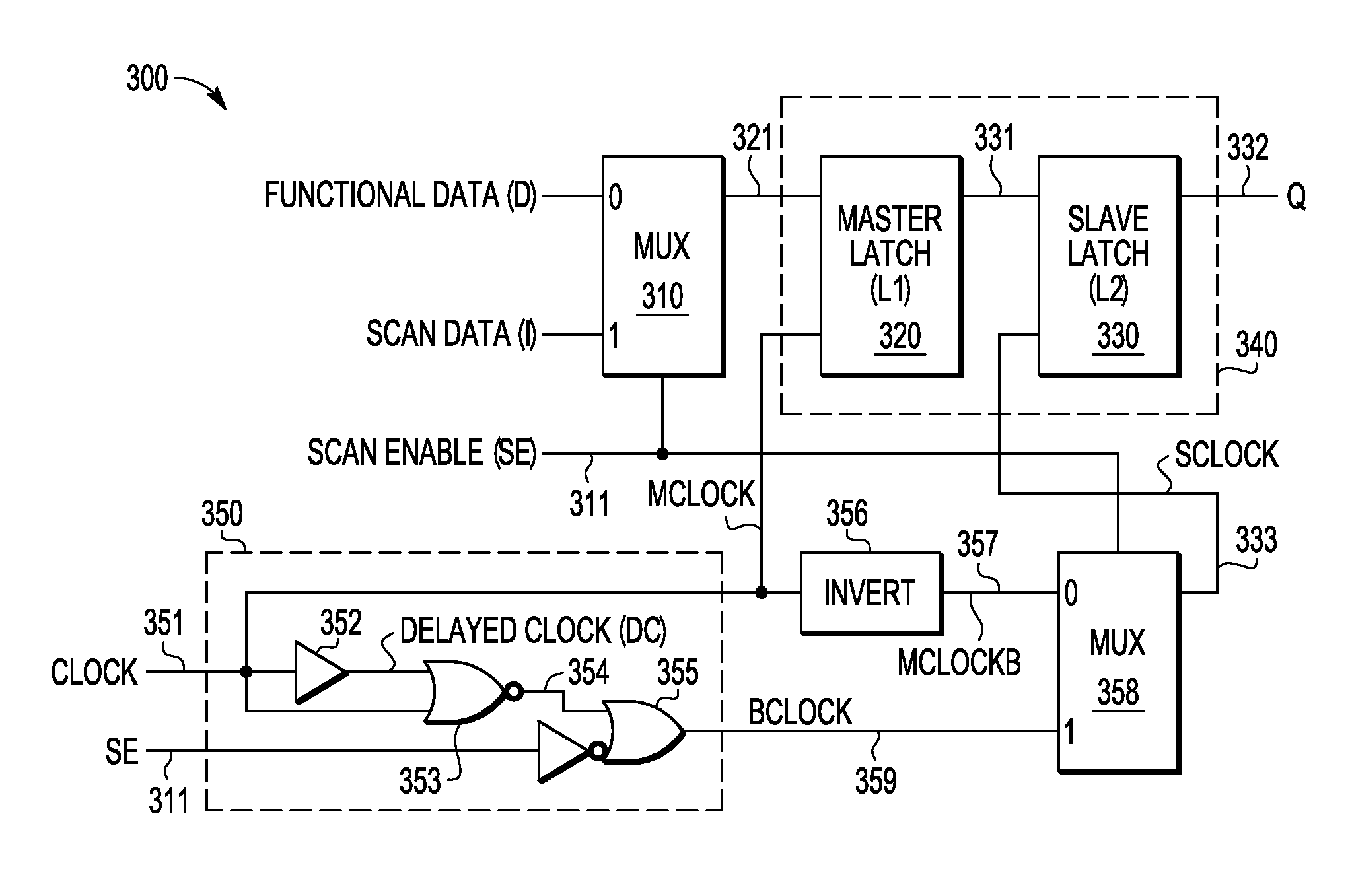
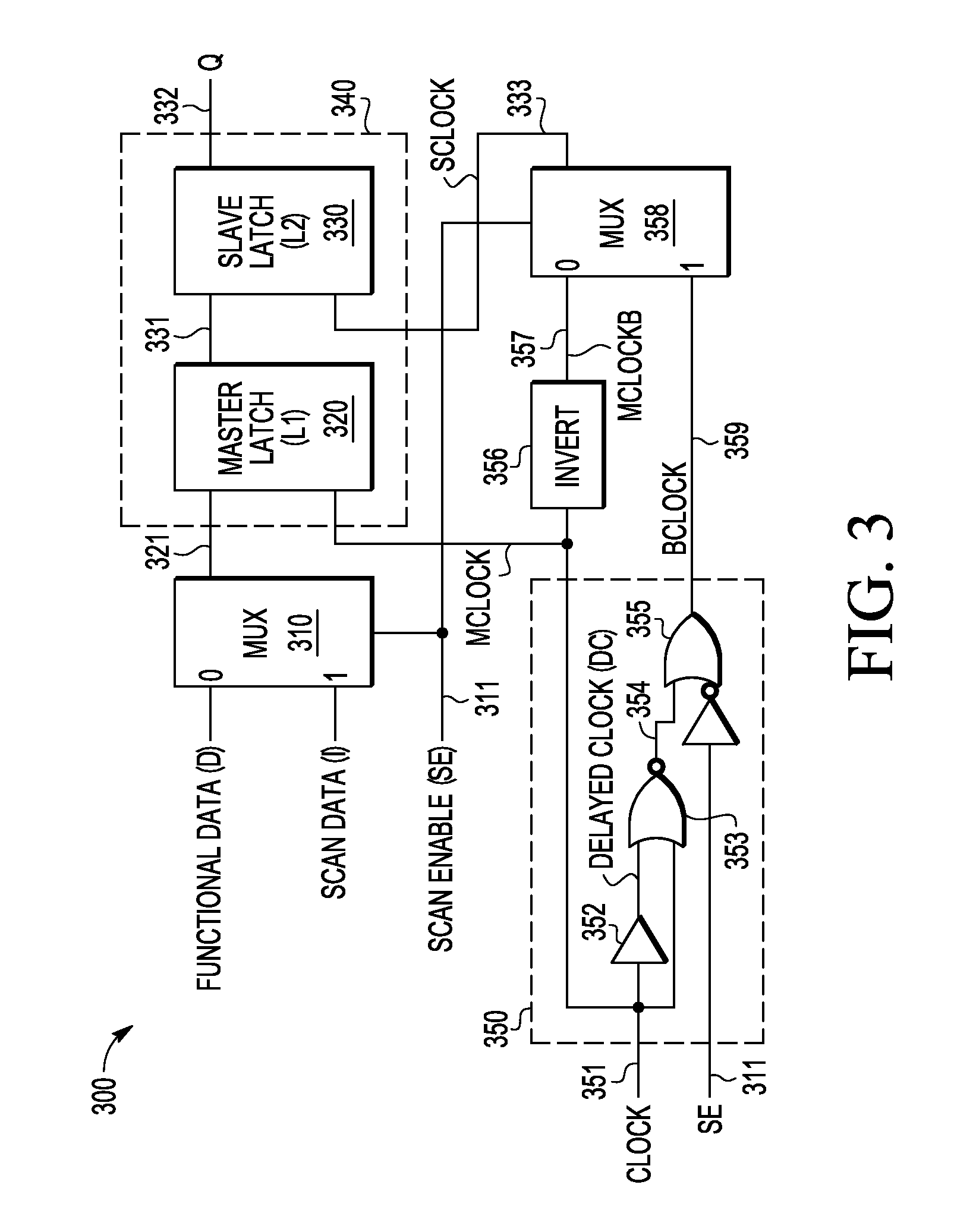
[0021]A multiplexed flip-flop with built-in structural hold and associated methodology of operation are described in connection with a separately clocked multiplexed data flip-flop which provides a Mux-D flip-flop behaviour during the functional mode and LSSD behaviour during the scan mode. To this end, an input clock signal that used for both functional and scan modes is used to generate a second clock that is a DC state during the functional mode and that switches during the scan mode. In the described embodiments, such an approach eliminates the need for hold buffers to fix hold violations in the scan path. In selected embodiments, the input clock signal and its inverse are applied to clock the master and slave latches during functional mode, but during scan mode, the input clock signal is used to generate a separate slave clock such that launch of the slave latch is substantially delayed with respect to the data capture by the master latch. In other embodiments, the input clock ...


PUM


Abstract

A multiplexed data flip-flop circuit (500) is described in which a multiplexer (510) outputs functional or scan data, a master latch (520) generates a master latch output signal at a hold time under control of a master clock signal, a slave latch (540) generates a flip flop output signal at a launch time under control of a slave clock signal, clock generation circuitry (550) generates a second clock signal that has a DC state during a functional mode and has a switching state during a scan mode, and data propagation logic circuitry (564) uses the first and second clock signals to generate the master and slave clock signals during a scan mode to delay the launch time of the slave latch with respect to the hold time of the master latch.

Description

BACKGROUND OF THE INVENTION[0001]1. Field of the Invention[0002]The present invention is directed in general to the field of electronic circuits. In one aspect, the present invention relates to a data latch apparatus and system for transferring data in a datapath and methods for operating same.[0003]2. Description of the Related Art[0004]In electronic circuits and data processing systems, flip-flops are commonly used in digital circuits for propagating data through various datapaths. Such flip-flops typically consist of master and slave latches, each of which uses its own clock for receiving data inputs and propagating data within the circuit / system. For example, the master latch captures input data during assertion of the capture clock, while the slave latch launches data during assertion of the launch clock. Testability typically requires the flip-flop to have an additional circuit portion that allows multiple flip-flops to be connected into a serial scan register chain for loadin...

Claims


Application Information

Patent Timeline
Patent Type & Authority Patents(United States)
IPC IPC(8): H03K19/173
CPCG01R31/318541
Inventor RAMARAJU, RAVINDRARAJBEARDEN, DAVID R.CROXTON, CODY B.KENKARE, PRASHANT U.
Owner NXP USA INC
Why Eureka
Try Eureka