Textile material comprising an HF transponder

a technology of transponder and textile, which is applied in the direction of weaving, washing apparatus, and using reradiation, etc., can solve the problems of inability to fully integrate an air coil in a textile layer, inability to meet the intended use, and inability to achieve the effect of reducing the danger of fractures at the antenna connection of the circuit modul

Active Publication Date: 2010-11-30
TEXTRACE AG
View PDF23 Cites 2 Cited by
  • Summary
  • Abstract
  • Description
  • Claims
  • Application Information

AI Technical Summary

Benefits of technology

[0032]Preferably in the production process of printing, the printing paste itself can be the conductive adhesive. In this way printing and producing the connection between the antenna connections and the radiator connections can be implemented in directly subsequent production steps in that the antenna connections are placed into the still moist printing paste that has not hardened yet. This obviates the need for an additional adhesive.
[0033]Furthermore, the adhesive surfaces of the adhesive connections can be UV-permeable, while the conductive adhesive is UV-curable. In this way the adhesive can be brought to cure in the entire adhesive region in a very short time by UV-radiation.
[0034]Preferably the circuit module itself and its antenna connections are enclosed by a casting compound, and the casting compound is at the same time connected to the region of the textile material that is adjacent to the circuit module. In this way the casting compound fixes the circuit module to the textile material because the casting compound penetrates the depths of the textile material as a result of capillary action. Separation is only possible by way of destruction so that tampering is detectable. Furthermore, the casting compound protects the circuit module also against mechanical and chemical influences. This additional fixing-in of the antenna connections provides protection to the contacts and at the same time provides pull relief to the radiator ends, as a result of which the danger of any fractures occurring at the antenna connections of the circuit module is reduced.
[0035]The E field radiator can be designed as a symmetrical dipole or as an asymmetrical bar with a counterweight. A dipole is associated with an advantage in that the circuit module can be connected without any adaptive measures to the feed-in point, directly to opened up conductive materials. However, in the case of a non-shortened half-wave dipole, a length that corresponds to half the wavelength of the working frequency is required for arranging the radiator.

Problems solved by technology

Combinations comprising a film layer and a textile layer, e.g. as laminates, are usually incompatible with the intended use and with the process of cleaning the textile goods.
Such film can become detached, partly or entirely, and / or can become damaged.
However, direct integration of an air coil in a textile layer, i.e. without a film carrier, is generally problematical due to the low-ohmic and narrow-band character of a coil antenna.
However, while embroidery techniques make it possible to produce a coil from a continuous electrically conductive thread, the reproducibility of the coil geometry and the stability of this geometry during intended use of the textile goods is very poor so that the resonance frequency of the coil cannot reliably be set to the working frequency and / or cannot be held constant.
However, with currently know techniques it is not possible to implement a coil antenna from a continuous electrically conductive thread in the form of a concentric spiral.
The transition resistance of each of these connections increases loss and negatively affects the coil quality.

Method used


Image

  • Textile material comprising an HF transponder
  • Textile material comprising an HF transponder
  • Textile material comprising an HF transponder

Examples


Embodiment Construction

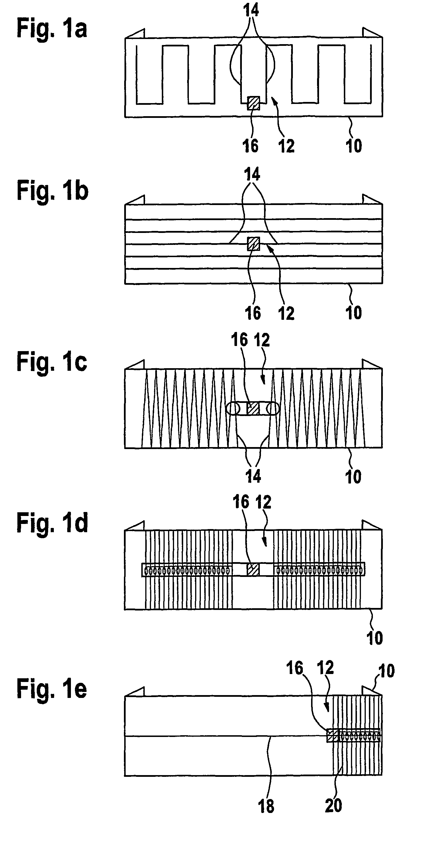
[0047]FIG. 1a is a top view of a textile label 10 with a transponder 12 that comprises a dipole antenna 14 as well as a circuit module 16 connected to the dipole 14 that has been opened up in the middle. The geometric length of the dipole 14 is shortened by half the wavelength of the working frequency of the transponder 12 and is electrically extended by inductive and capacitive contents. This has been implemented by a meandering structure of the electrical conductor of the dipole antenna 14. In the case of embroidery techniques, weaving techniques or printing techniques this can be achieved by a continuous electrically conductive thread or by a continuous conductive printed track. In the case of weaving techniques this is also possible by combining electrically conductive warp threads with weft threads, wherein said threads are interconnected at points of intersection, whereas for the remainder they are electrically insulated from the other regions.

[0048]In FIG. 1b the dipole 14 is...


PUM

PropertyMeasurementUnit
frequencyaaaaaaaaaa
frequencyaaaaaaaaaa
frequencyaaaaaaaaaa

Abstract

The invention relates to a textile material that comprises an HF transponder. The HF transponder comprises a circuit module and an antenna linked therewith and set to a working frequency. The antenna is configured as an E field radiator for a working frequency in the UHF or microwave range. The E field radiator is completely constituted of electrically conducting components of the textile material itself.

Description

CROSS REFERENCE TO RELATED APPLICATIONS[0001]Applicant claims priority under 35 U.S.C. §119 of German Application No. 10 2004 003 461.3 filed Jan. 22, 2004. Applicant also claims priority under 35 U.S.C. §365 of PCT / DE2005 / 000041 filed Jan. 14, 2005. The international application under PCT article 21(2) was not published in English.BACKGROUND OF THE INVENTION[0002]1. Field of the Invention[0003]The invention relates to a textile material with an HF transponder according to the precharacterising part of claim 1.[0004]To identify goods during production, logistics, distribution and repair, increasingly transponders are used that in relation to legibility and data volume, as well as manipulation reliability, are superior to common barcodes. The use of transponders is also striven for in the case of textile goods; however, due to their flexible character and the necessity to clean them in hot and / or chemically corrosive media, the requirements are more stringent.[0005]For example, a tra...

Claims


Application Information

Patent Timeline
Patent Type & Authority Patents(United States)
IPC IPC(8): H01Q1/36H01Q9/16A41D1/00D03D15/00D06F93/00E05B73/00G06K19/02G06K19/04G06K19/077H01Q1/27
CPCG06K19/02G06K19/027G06K19/041G06K19/07749G06K19/07786H01Q1/273H01Q1/36H01Q9/16
Inventor STOBBE, ANATOLI
Owner TEXTRACE AG
Why Eureka
Try Eureka