Hydraulic lash adjuster with damping device

a technology of damping device and lash adjuster, which is applied in the direction of mechanical equipment, engine components, machines/engines, etc., can solve the problems of difficult tuning or adapting the response to a particular valve train system, unsatisfactory operation or engine damage, and conventional lash adjuster design that does not allow explicit control of the damping characteristics of the adjustment system, etc., to achieve better control of valve opening and closing events, facilitate tuning of the lash adjuster response, and reduce nois

Inactive Publication Date: 2010-12-07
FORD GLOBAL TECH LLC
View PDF25 Cites 10 Cited by
  • Summary
  • Abstract
  • Description
  • Claims
  • Application Information

AI Technical Summary

Benefits of technology

[0006]The present disclosure includes embodiments having various advantages. For example, the system and method of the present disclosure incorporate a hydraulic damper into the design of the lash adjuster with either a normally closed, normally open, or free-ball lash adjuster suitable for overhead cam or pushrod engines. Controlling flow passage geometry and / or damper chamber volume facilitates tuning of the lash adjuster response for particular valvetrain designs and / or operating conditions. Response time tuning of the lash adjuster using the damping device may facilitate better control over valve opening and closing events, valve duration, and valve lift. In addition, a tunable response may be used to better match the characteristics of a particular valvetrain design to reduce noise, vibration, and harshness (NVH). The tunable damping feature of the present disclosure may be used to compensate for valve growth during aggressive cold start strategies while providing a more robust control system that is less sensitive to variations in oil temperature and viscosity.

Problems solved by technology

If the duration of the unloading event is longer than the time required for the lash adjuster to respond and increase the hydraulic fluid volume within the high pressure chamber, the lash adjuster may prevent the valve from closing properly, which could result in undesirable operation or engine damage.
Conventional lash adjuster design does not allow for explicit control of the damping characteristics of the adjustment system.
While this approach may be suitable for many applications, it may be difficult to tune or adapt the response to a particular valve train system.

Method used


Image

  • Hydraulic lash adjuster with damping device
  • Hydraulic lash adjuster with damping device
  • Hydraulic lash adjuster with damping device

Examples


Embodiment Construction

)

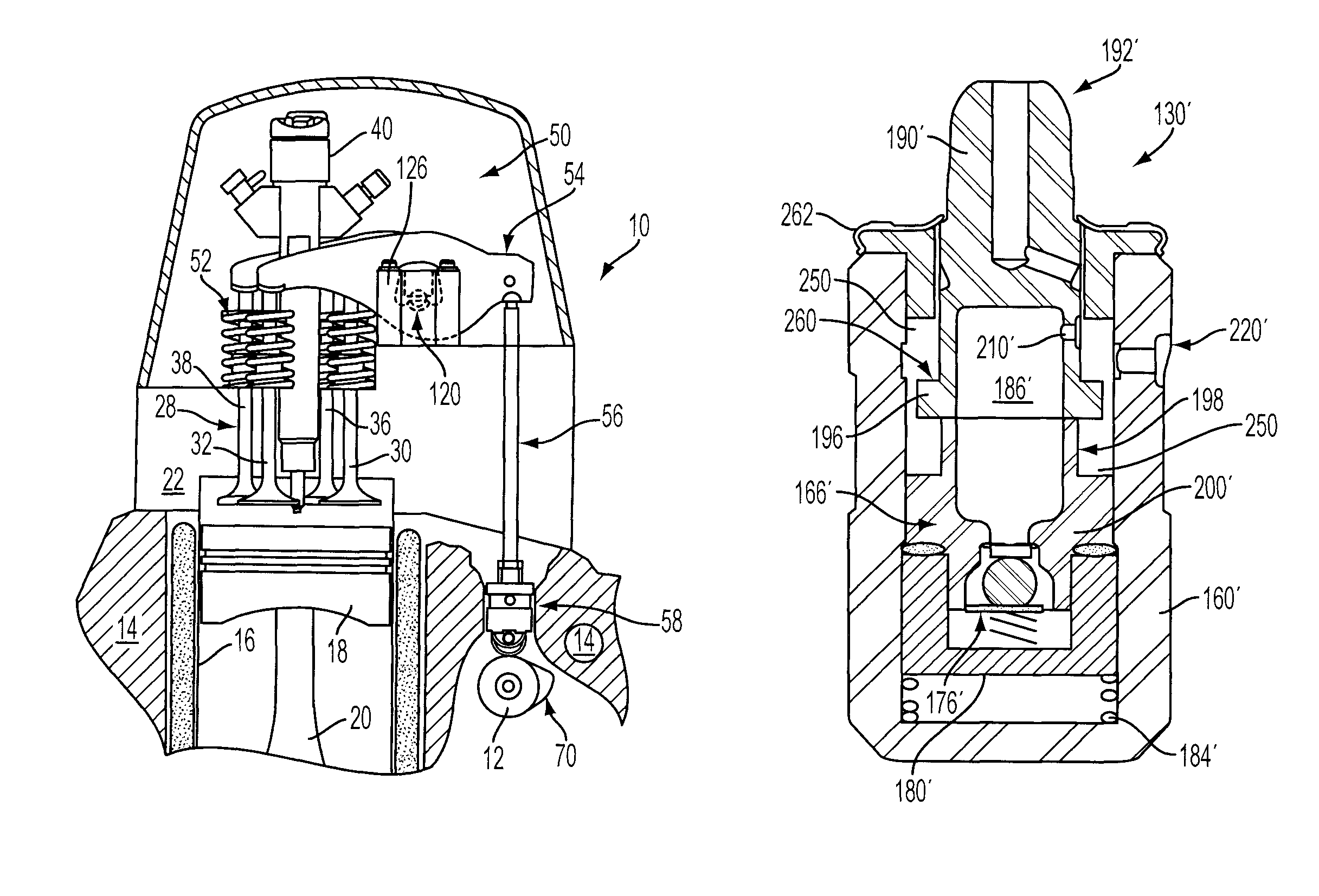
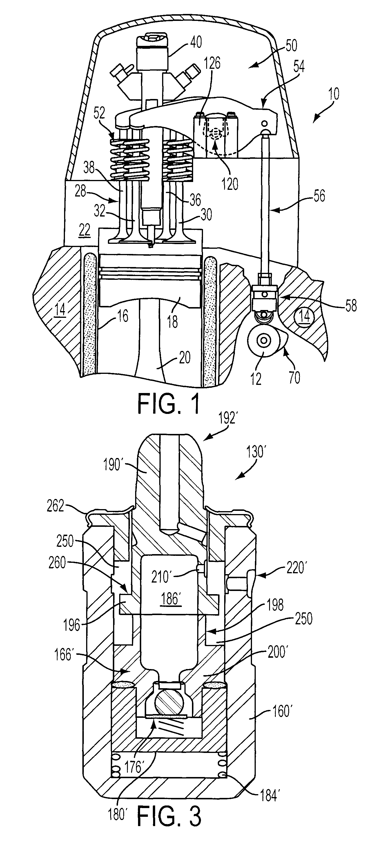
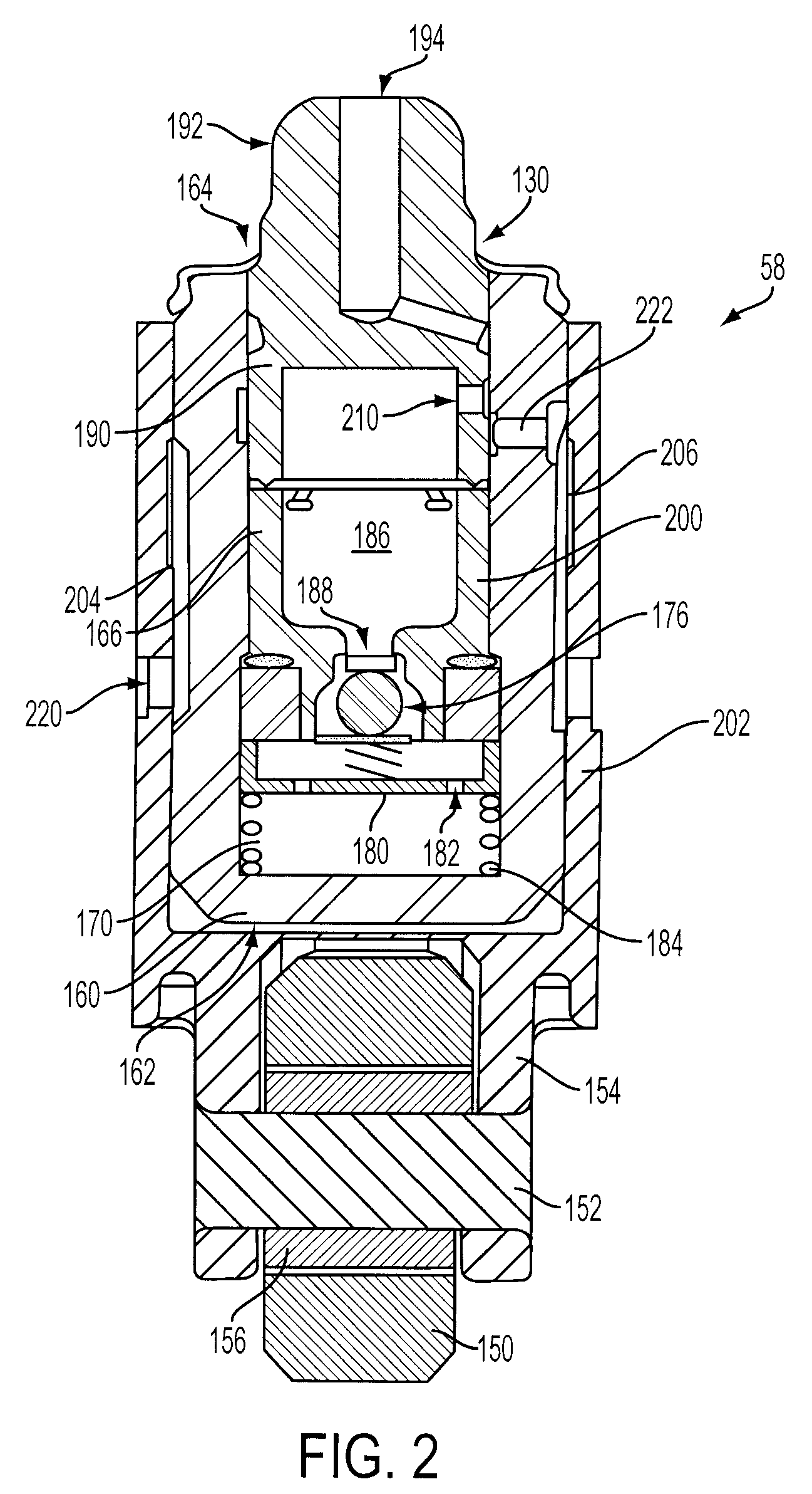
[0013]As those of ordinary skill in the art will understand, various features of the embodiments illustrated and described with reference to any one of the Figures may be combined with features illustrated in one or more other Figures to produce alternative embodiments that are not explicitly illustrated or described. The combinations of features illustrated provide representative embodiments for typical applications. However, various combinations and modifications of the features consistent with the teachings of the present disclosure may be desired for particular applications or implementations. The representative embodiments used in the illustrations relate generally to a hydraulic lash adjuster for the valvetrain of a four-stroke, multi-cylinder, internal combustion engine. Those of ordinary skill in the art may recognize similar applications or implementations with other engine / vehicle technologies.

[0014]FIGS. 1-5 illustrate operation of a hydraulic lash adjuster for the valve...


PUM


Abstract

A system and method for lash adjustment in the valvetrain of an internal combustion engine include a hydraulic lash adjuster having a damping device to limit rate of movement of a plunger relative to a body to control response time of the lash adjuster reducing or eliminating over-compensation or pump-up of the lash adjuster.

Description

BACKGROUND[0001]1. Technical Field[0002]The present disclosure relates to a hydraulic lash adjuster with a damping device for use in an internal combustion engine valvetrain.[0003]2. Background Art[0004]Modern valvetrain systems use hydraulic lash adjusting elements to compensate for valve train wear, thermal expansion during engine warm-up, and any other phenomena that change clearances within the valve train mechanical linkage. Hydraulic lash adjusters use hydraulic fluid within a variable volume pressure chamber behind a plunger to transmit the valve actuating force from a camshaft to the rocker arm. The volume of fluid within the chamber changes to move the plunger and remove the clearance or lash within the mechanical linkage of the valvetrain. Under some operating conditions or in particularly compliant valvetrains, the lash adjuster may “pump-up” or over compensate by allowing too much hydraulic fluid into the pressure chamber during events where rapid unloading of the mechan...

Claims


Application Information

Patent Timeline
Patent Type & Authority Patents(United States)
IPC IPC(8): F01L1/14
CPCF01L1/053F01L1/146F01L1/182F01L1/24F01L3/08F01L1/2405F01L1/185Y10T74/2107F01L2001/054F01L2001/2427F01L2105/00F01L2305/00
Inventor TALLIO, KEVIN V.LYJAK, JEFF CHESTERCOMER, FLOYD MELVIN
Owner FORD GLOBAL TECH LLC
Why Eureka
Try Eureka