Projector apparatus

a projector and apparatus technology, applied in the field of projector apparatus, can solve the problems of bothering the user of the projector, affecting the use of the projector, and causing the noise of fans, so as to reduce the noise of the inventive projector apparatus, reduce the cost of the projector apparatus, and reduce the noise of the exhaust unit

Active Publication Date: 2010-12-07
SANYO ELECTRIC CO LTD +1
View PDF14 Cites 21 Cited by
  • Summary
  • Abstract
  • Description
  • Claims
  • Application Information

AI Technical Summary

Benefits of technology

[0004]It is, therefore, an object of the present invention to provide a projection apparatus having a reduced number of fans such that they need not be operated at high speeds, yet they are capable of exhausting air at a low temperature.
[0019]a cooling duct provided on the expiration side of the second fan to cool the light source and optical system.
[0020]This arrangement enhances exhaustion of the internal air and lowers the internal pressure, which in turn accelerates suction of external air.
[0021]In this case, the cooling duct may include a multiplicity of bifurcating cooling ducts, so that the second fan can cool the light source and different components of the optical system using the multiplicity of bifurcating cooling ducts.
[0028]Thus, in accordance with the present invention, exhaust air temperature can be lowered to at least the same level as a conventional temperature even if the fans are in operation at reduced rotational speed and / or if a fewer number of fans are in operation than a conventional exhaust unit.
[0029]Accordingly, it is possible to reduce the noise created by the exhaust unit. For example, the noise of the inventive projector apparatus can be improved to the level as low as 30 dB when the lamp has a luminosity of 2000 lm. Further, in order to reduce the cost of a projector apparatus, it is possible to use quartz as the base material of polarization plates and further reduce the number of fans of the projector apparatus. Further, in order to reduce the cost of a projector apparatus, it is possible to use quartz as the base material of polarization plates and further reduce the number of fans of the projector apparatus.

Problems solved by technology

Since the exhaust unit is orientated to the hot lamp so as to inspire air heated by the lamp, the air discharged from the exhaust unit is heated to a high temperature, which makes the user of the projector unpleasant when he is exposed to the hot air.
Hence, in order to lower the temperature of the exhausted air, the exhaust fan of the exhaust unit must be operated at a high speed, which in turn creates a bothering noise.
Moreover, a multiplicity of fans other than the exhaust fan are installed in some instance, where those fans create and leak unpleasant noises even if they are operated at low speed, since they are usually located at peripheral corners of the apparatus.
Furthermore, the increase in number of the fans and related manufacturing steps results in additional assembly cost, which inevitably raises the cost of the apparatus.

Method used


Image

  • Projector apparatus
  • Projector apparatus
  • Projector apparatus

Examples


Embodiment Construction

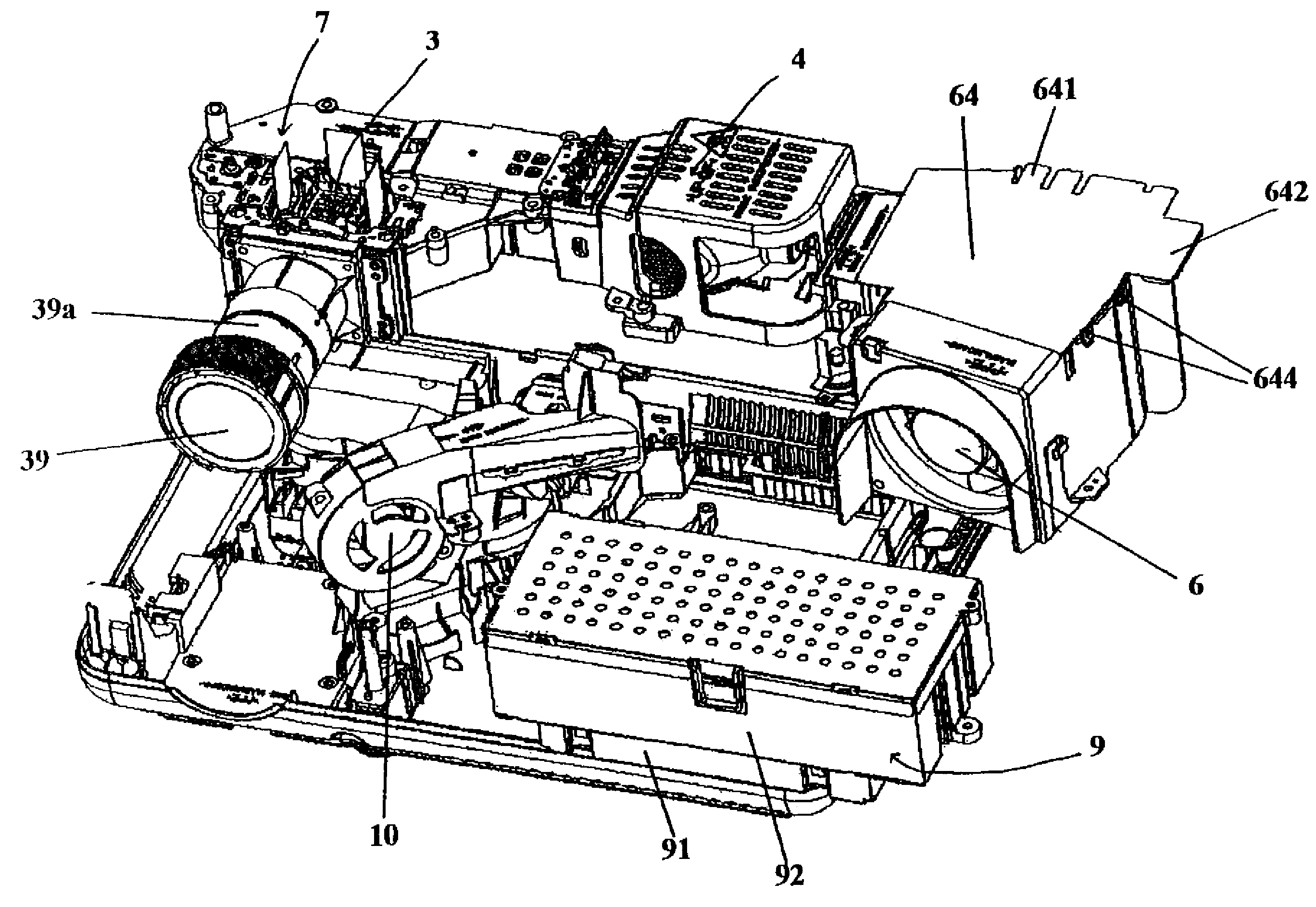
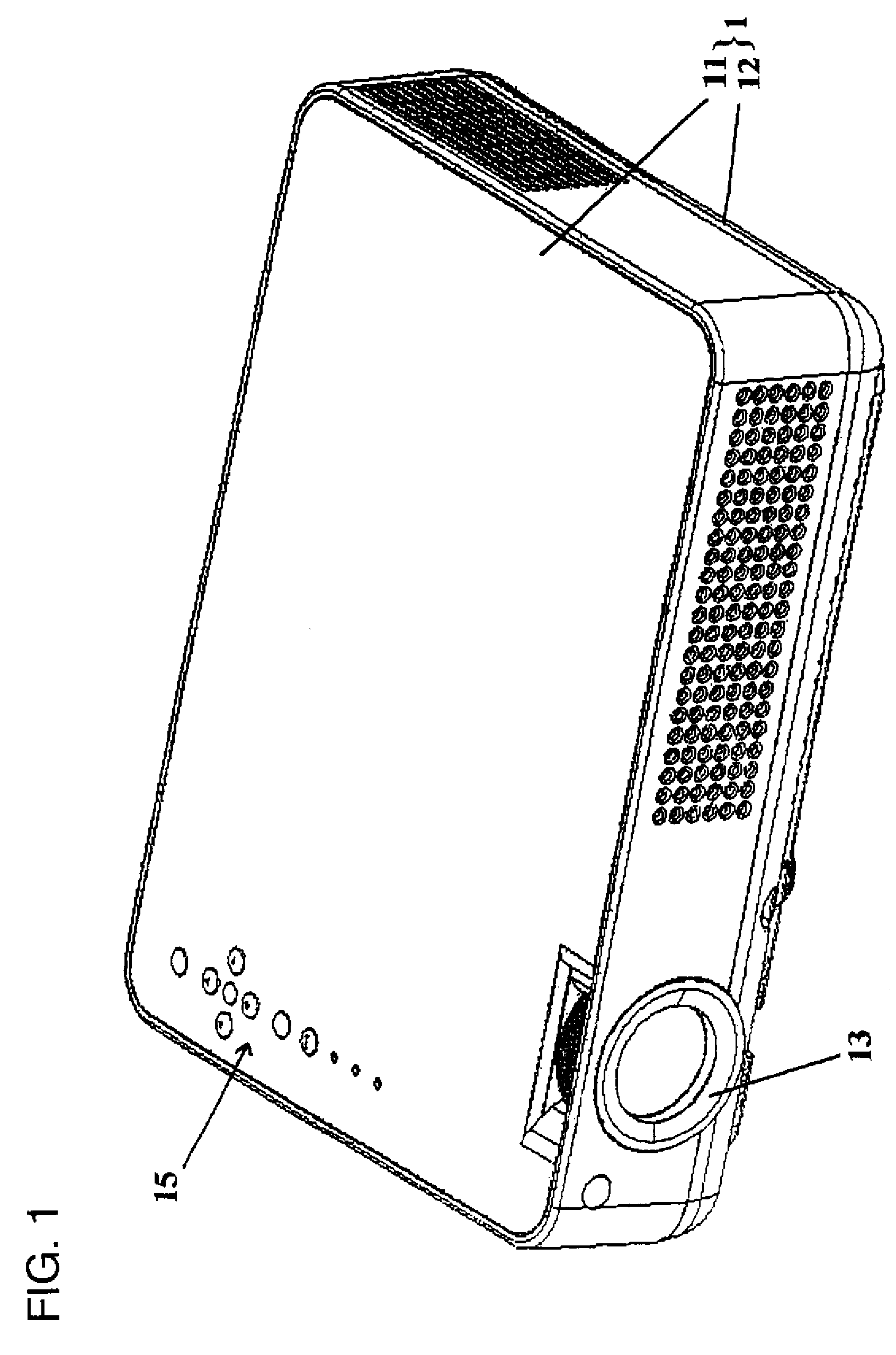
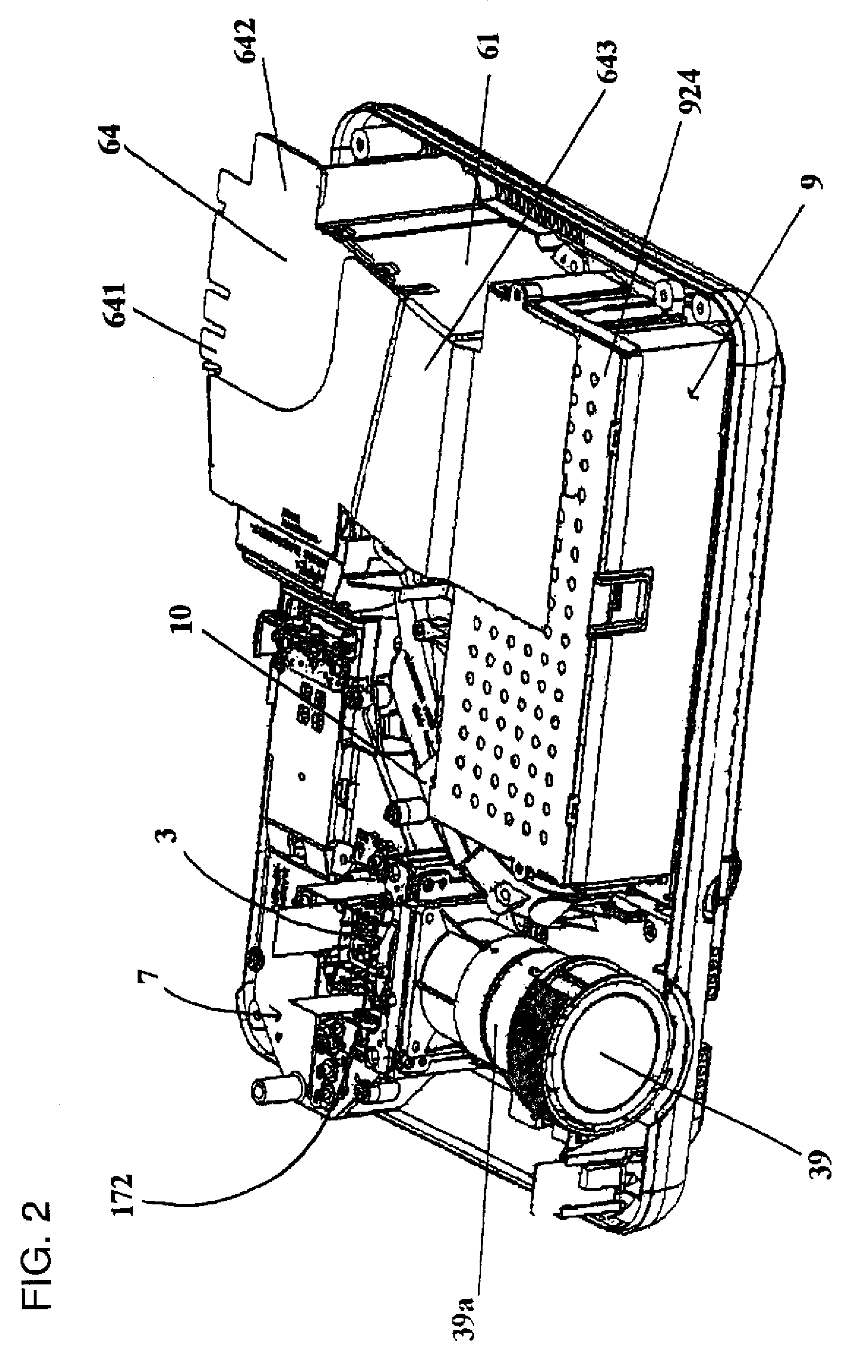
[0062]The invention will now be described in detail by way of example, particularly an LC projector apparatus and related parts, with reference to the accompanying drawings. In what follows, the “front” side of the projector apparatus refers to the side thereof having its projection lens (FIG. 1), and the “right” and “left” of the LC projector apparatus refer to the directions to the “right” and “left” relative to the front side, respectively. It should be understood that terms indicating relative positions of elements such as “bottom”, “side”, “oblique”, and “directly below” are illustrative, and that the relative positions can be conveniently altered as needed.

Overall Arrangement

[0063]The LC projector apparatus is provided with a generally flat casing 1 which consists of an upper half section 11 and a lower half section 12, as shown in FIG. 1. Provided on the upper end of the casing 1 is a controller 15 having a multiplicity of buttons for manual operation of the projector apparat...


PUM


Abstract

The invention enables efficient cooling of: a light source providing source light; an optical system adapted to split the source light received from the light source into three primary colors R, G, and B; and a power supply unit for supplying electric power to various electric components installed in a casing of a projector apparatus. To do so, a first fan is arranged between the light source and the power supply unit such that its air inspiration face is directed to the power supply unit and its air expiration face is directed to the light source. Further, a second fan, adapted to inspire air from within the projector apparatus, is provided in the central area of the projector apparatus. On the air expiration side of the second fan is a cooling duct for cooling the light source and optical system. In addition, a third fan for cooling a G-LCP unit and an R-LCP unit of the image synthesizing device and a fourth fan for cooling a B-LCP and an R-LCP unit of the image synthesizing device are provided in such a way that the streams of air expired from said third and fourth fans intersect each other. The invention allows operation of a projector apparatus with a fewer fans, yet achieves suppression of exhaust air temperature and noise, and cost reduction as well.

Description

FIELD OF THE INVENTION[0001]Present invention relates to a projector apparatus equipped with an optical system adapted to construct imaging light from light received from a light source and project an enlarged beam of imaging light onto a front screen.BACKGROUND OF THE INVENTION[0002]Japanese Patent Application Laid Open No. H8-275096 discloses a projector apparatus equipped with a lamp serving as a light source and an optical system having such elements as a polarization prism substrate, polarization plates, liquid crystal panels (LCPs), and a projection lens, all housed in a casing. Provided on a wall of the casing is an exhaust unit adapted to create an air flow inside the casing to suppress temperature rise in the casing.[0003]Since the exhaust unit is orientated to the hot lamp so as to inspire air heated by the lamp, the air discharged from the exhaust unit is heated to a high temperature, which makes the user of the projector unpleasant when he is exposed to the hot air. Henc...

Claims


Application Information

Patent Timeline
Patent Type & Authority Patents(United States)
IPC IPC(8): G03B21/16
CPCG03B21/14G03B21/16G03B21/22H04N9/3105H04N9/3144H04N9/3197G03B21/145
Inventor LV, QIANGZHANG, XIANGLINSARUWATARI, TOSHIHIROHUANG, YANSHANRENBUTSU, TADASHIOKAZAKI, SHOJIKONG, XIANGFEITANG, WENTIAN
Owner SANYO ELECTRIC CO LTD
Why Eureka
Try Eureka