
Bi-directional DC-DC converter and method for controlling the same

a dc-dc converter and bi-directional technology, applied in the direction of electric variable regulation, process and machine control, instruments, etc., can solve the problems of becoming an obstacle to preventing the realization of miniaturization and high efficiency, so as to achieve the effect of large electric power

Inactive Publication Date: 2010-12-07
HITACHI INFORMATION & TELECOMM ENG LTD
View PDF7 Cites 34 Cited by
  • Summary
  • Abstract
  • Description
  • Claims
  • Application Information

AI Technical Summary

Benefits of technology

[0018]According to the embodiment of the invention, the control means controls a time which is necessary until the upper or lower arm switching element in the ON state is switched to OFF and the energy is supplied to the first DC power source after the switching elements in the ON state in the first switching element group were switched to OFF, thereby adjusting an amount of energy which is supplied to the first DC power source.

Problems solved by technology

In the bi-directional DC-DC converter in the related art disclosed in JP-A-2002-165448, since not only the efficiency is deteriorated by a loss due to a circulating current at the time of the step-down operation but also it is necessary to raise a withstanding voltage of the switching element by surge voltages caused in the low voltage side circuit at the time of the step-up / down operations, they become an obstacle to realization of miniaturization and high efficiency.
In the bi-directional DC-DC converter in the related art disclosed in Patent Document 2 (JP-A-2006-187147), when a step-up voltage ratio / output electric power is large at the time of the step-up operation, it is also necessary to raise the withstanding voltage of the switching element in the low voltage side circuit and it becomes an obstacle to realization of miniaturization and high efficiency.

Method used


Image

  • Bi-directional DC-DC converter and method for controlling the same
  • Bi-directional DC-DC converter and method for controlling the same
  • Bi-directional DC-DC converter and method for controlling the same

Examples


Embodiment Construction

[0038]An embodiment of the invention will be described in detail with reference to the drawings. The same or corresponding portions in the drawings are designated by the same reference numerals. In the embodiment, although it is assumed that an IGBT and a MOSFET are used as switching elements as an example, the invention is not limited to them. A voltage of the switching element in an ON state or a voltage which is almost equal to or lower than a forward drop voltage of a diode is assumed to be a zero voltage.

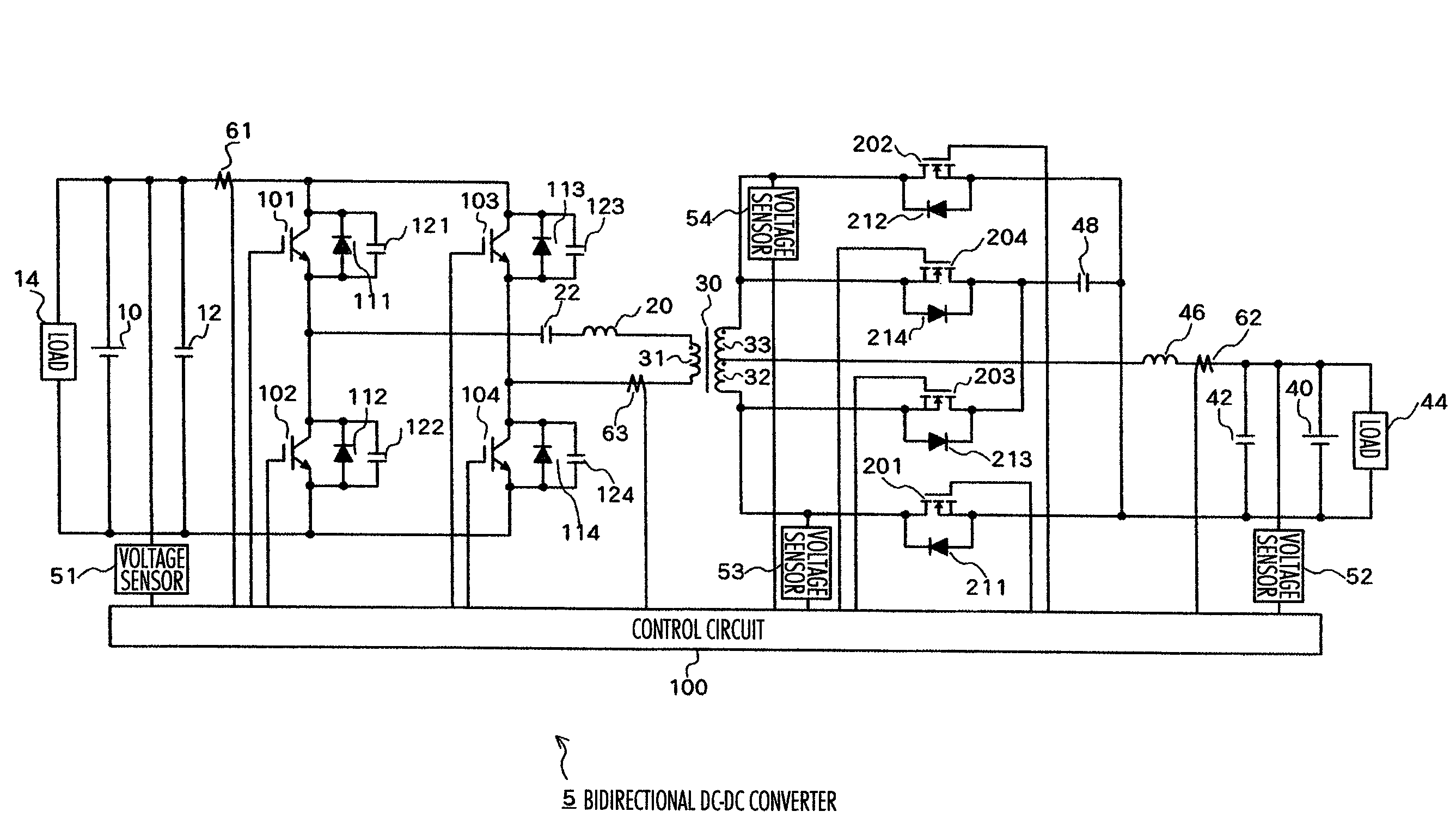
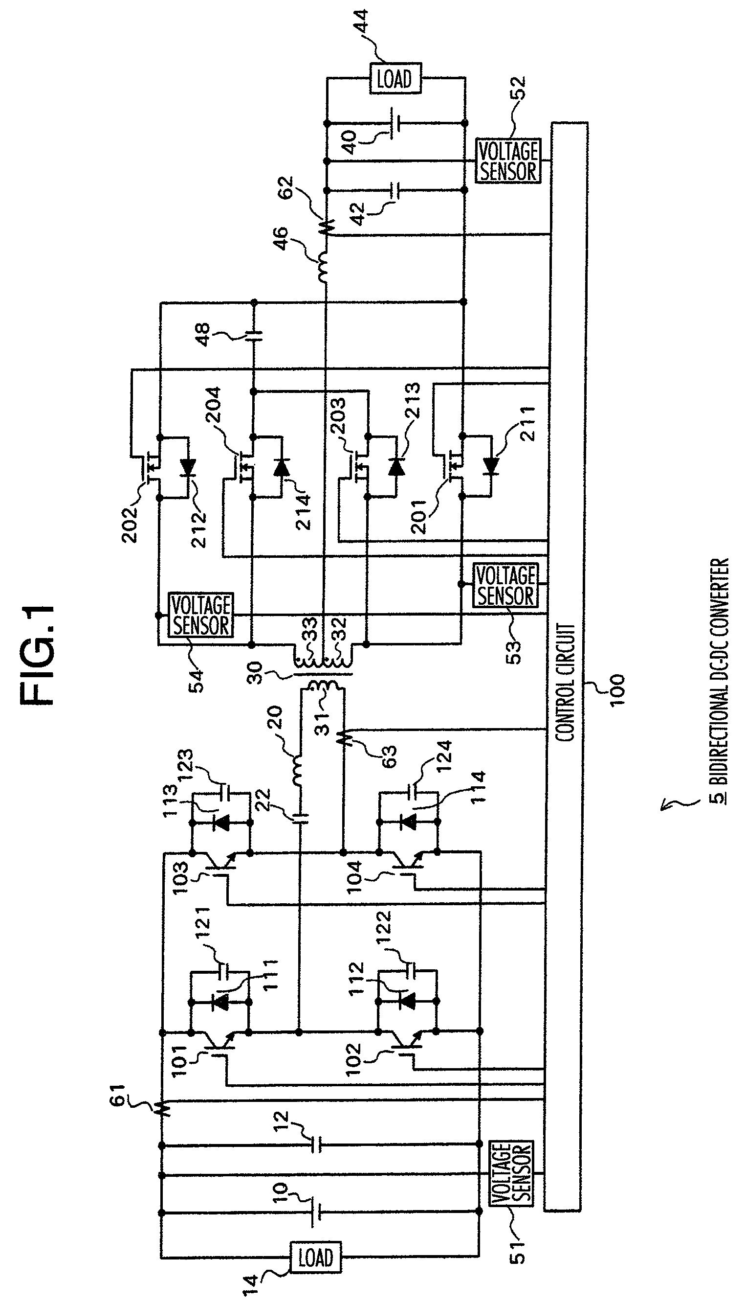
[0039]FIG. 1 is a circuit constructional diagram of a bi-directional DC-DC converter 5 according to the embodiment of the invention. In FIG. 1, a smoothing capacitor 12, a load 14, a first switching arm in which an emitter of an IGBT 101 and a collector of an IGBT 102 are connected, and a second switching arm in which an emitter of an IGBT 103 and a collector of an IGBT 104 are connected are connected in parallel to a power source 10 on a high voltage side.

[0040]Each of diodes ...


PUM


Abstract

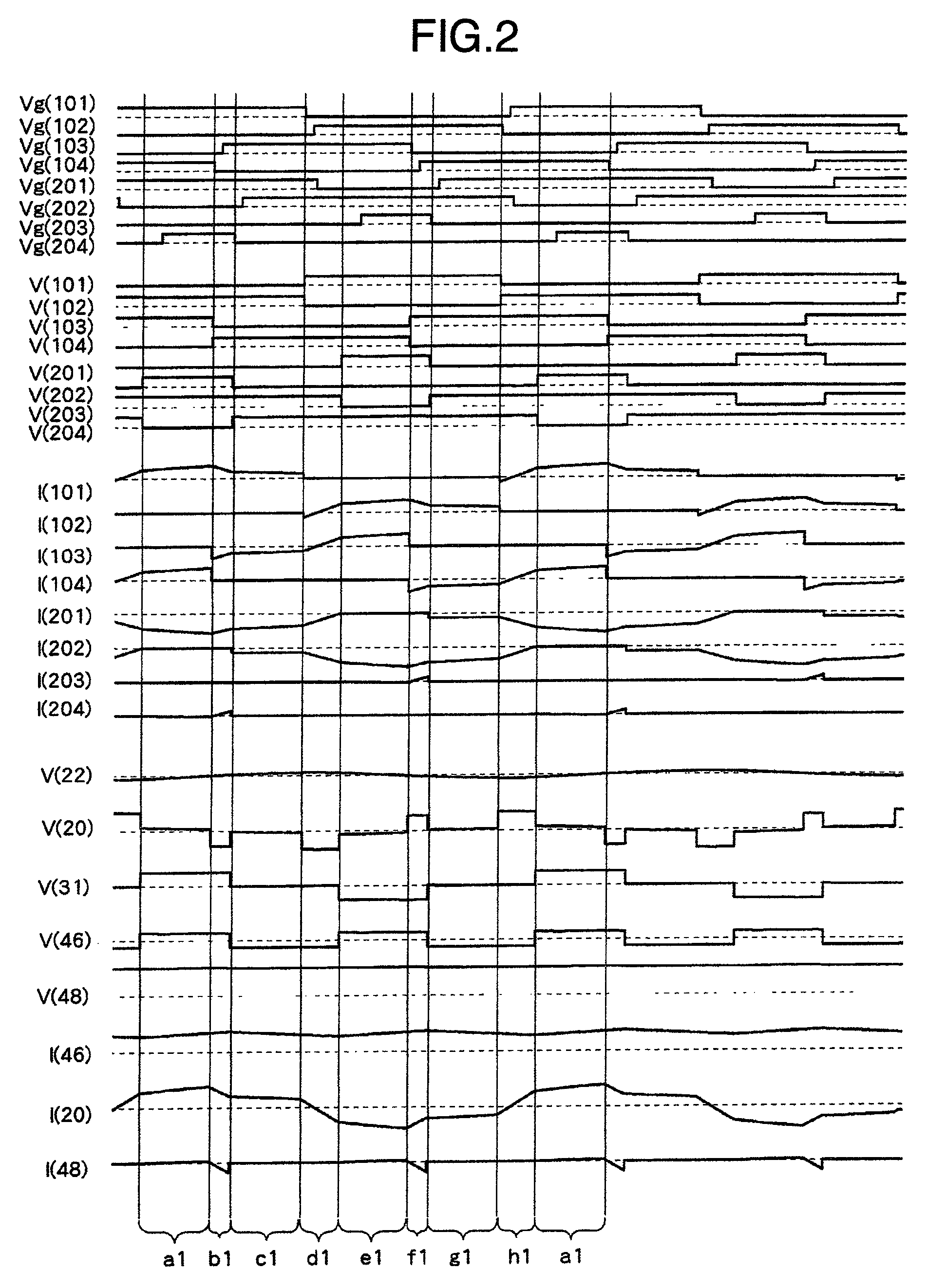
A bi-directional DC-DC converter has a transformer for connecting a voltage type full bridge circuit connected to a first power source and a current type switching circuit connected to a second power source. A voltage clamping circuit constructed by switching elements and a clamping capacitor is connected to the current type switching circuit. The converter has a control circuit for cooperatively making switching elements operative so as to control a current flowing in a resonance reactor.

Description

BACKGROUND OF THE INVENTION[0001]1. Field of the Invention[0002]The invention relates to a bi-directional DC-DC converter having an insulating function and a method for controlling such a converter.[0003]2. Description of the Related Arts[0004]In recent years, hybrid vehicles having high efficiency have been being spread due to an increase in consciousness of conservation of the global environment. The hybrid automobile has a main battery for driving a motor and a battery for auxiliaries. If an electric power can be mutually supplied between the two batteries of different voltages, design flexibility of a vehicle power supply systems can be increased.[0005]A bi-directional DC-DC converter for bi-directionally converting electric powers between two power sources of different voltages has been disclosed in JP-A-2002-165448. In the bi-directional DC-DC converter disclosed in Patent Document 1, a voltage type circuit on a high voltage side and a current type circuit on a low voltage sid...

Claims


Application Information

Patent Timeline
Patent Type & Authority Patents(United States)
IPC IPC(8): H02M3/335H02H7/10
CPCH02M3/33584H02M1/32H02M1/0058Y02B70/10
Inventor SHIMADA, TAKAETAKAHASHI, YOSHIHIDETANIGUCHI, KIMIAKISHOJI, HIROYUKI
Owner HITACHI INFORMATION & TELECOMM ENG LTD
Learn More