Blood vessel closure clip and delivery device

Inactive Publication Date: 2010-12-14
ABBOTT CARDIOVASCULAR
View PDF801 Cites 80 Cited by
  • Summary
  • Abstract
  • Description
  • Claims
  • Application Information

AI Technical Summary

Benefits of technology

[0016]The advantage of such devices are that they are significantly simpler to operate than previously described mechanical closure devices. In addition, the mode of operation of the balloon device is consistent with that of other devices used by interventional radiologists and cardiologists in that it provides a catheter delivered over a guide wire with a balloon which is inflated from an external port.

Problems solved by technology

The problems associated with this device are the significant number of steps in its use, tying of the suture loop involves a sawing action around the puncture hole which could unintentionally cause the suture to cut its way through the hole, pushing needles from outside the artery to inside creates two additional puncture holes and finally a loop of suture remains inside the artery and has the potential to dislodge plaque within the artery.
Problems associated with this device include the use of a specialised sheath which must be inserted over the guide wire and advanced into the tissue tract before the closure procedure can take place.
In addition delicate stabiliser type devices must be deployed within the artery before the stapler can be delivered to close the puncture hole.
While both devices described above are effective in terms of closing puncture holes they are mechanically complex in nature in terms of operation.

Method used


Image

  • Blood vessel closure clip and delivery device
  • Blood vessel closure clip and delivery device
  • Blood vessel closure clip and delivery device

Examples


Embodiment Construction

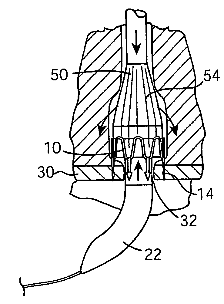
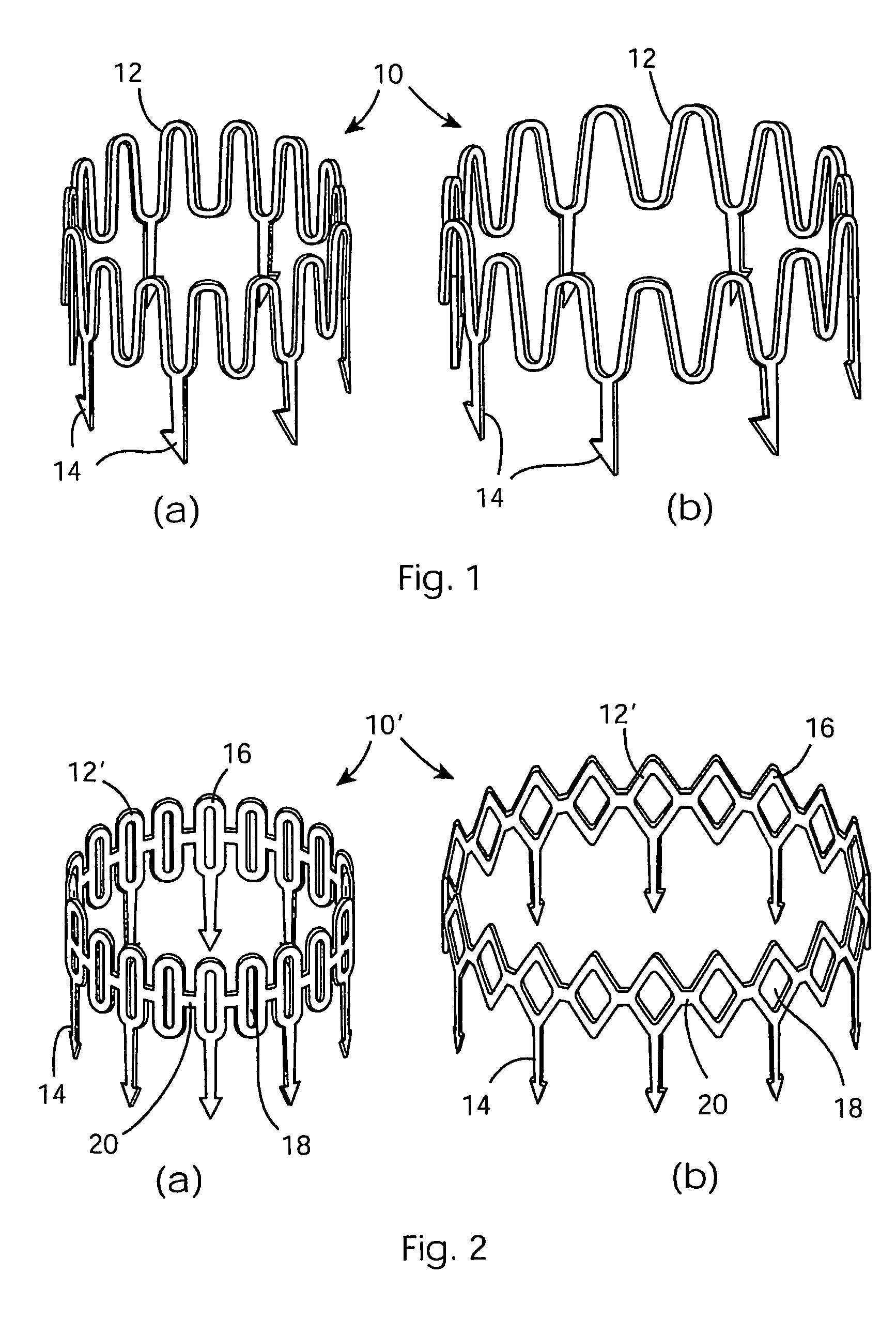
[0031]Referring first to FIG. 1, a ring occluder 10 for closing a puncture hole in a blood vessel comprises a circumferentially continuous metal ring 12. The circumference of the ring 12 is sinuous and the ring has a plurality of sharp metal prongs 14 extending at least approximately in the same direction from one edge (in FIG. 1 the lower edge) of the ring 12. The prongs are 3-5 mm in length and extend from alternate minima of the sinuous shape. The prongs 14 are barbed, meaning in the present context that they are configured to resist withdrawal once they penetrate tissue. The prongs 14 preferably mutually converge slightly towards the centre axis of the ring 12. FIG. 1(a) shows the ring occluder in its non-expanded state, while FIG. 1(b) shows the ring occluder in its expanded state where the pitch between the peaks of the sinuous configuration have been increased in a manner which provides uniform expansion of the ring at all points on its circumference. The pitch between the ba...


PUM


Abstract

A clip for closing a puncture hole in a blood vessel comprises a ring 12 having a resiliently expandable circumference and a plurality of barbed prongs 14 extending at least approximately in the same direction from one edge of the ring. A device for deploying such a clip is also described.

Description

[0001]This application is a 371 of PCT / IE03 / 00088, filed on Jun. 4, 2003.FIELD OF THE INVENTION[0002]This invention relates to a clip for closing a puncture hole in a blood vessel, and to a device for closing a puncture hole using such a clip.BACKGROUND[0003]Numerous medical diagnostic and interventional procedures involve the use of long catheters which are placed within the human vascular system. These catheters are delivered over guide wires to positions in the heart for cardiac procedures and into the brain for neurological procedures. The point of entry is normally a puncture hole in the femoral artery in the patient's groin. Once the procedure has been completed the catheter and guide wire are removed and the puncture hole must be closed in order to prevent excessive bleeding and the possibility of infection. Traditionally this puncture hole has been closed by maintaining manual pressure at the puncture site until homeostasis occurs around the puncture hole or placing sand bag...

Claims


Application Information

Patent Timeline
IPC IPC(8): A61B17/08A61B17/12A61B17/00A61B17/064A61B17/068A61B17/122A61B17/128A61B17/22
CPCA61B17/0057A61B17/064A61B17/083A61B17/0644A61B17/068A61B2017/00292A61B2017/00557A61B2017/00637A61B2017/00668A61B2017/0641A61B2017/22061A61B2017/00867
Inventor CUMMINSSTEVENSON, ROBERT
Owner ABBOTT CARDIOVASCULAR
Why Eureka
Try Eureka