Particle separator and method for removing particles from an exhaust gas stream of an internal combustion engine

a technology of particle separator and exhaust gas stream, which is applied in the direction of exhaust treatment, solid separation, phosphorus compounds, etc., can solve the problems of increased fuel consumption, particle emissions, and high exhaust gas counter pressure caused by filters, and achieve the effect of easy perforation

Active Publication Date: 2010-12-14
MAN TRUCK & BUS AG
View PDF12 Cites 13 Cited by
  • Summary
  • Abstract
  • Description
  • Claims
  • Application Information

AI Technical Summary

Benefits of technology

[0014]So that the particle separator can form these differing flow regions, the particle separator can be provided with means for accelerating and / or slowing down and / or deflecting the exhaust gas stream in the particle separator. Several possibilities can be provided to accomplish this. It is particularly straightforward and advantageous to form the differing flow regions by, for example, differently sized free flow cross-sections. In this connection, as viewed in the direction of flow of the exhaust gas stream, the differing flow regions can be disposed one after another and / or next to one another and / or one above another, depending upon the concrete construction of the particle separator. It is particularly important in this connection, especially in conjunction with those flow regions that have a high flow velocity of the exhaust gas stream, that in addition means be provided by means of which the exhaust gas stream in the particle separator can be repeatedly deflected and / or split into partial exhaust gas streams in order in a straightforward manner, with a high functional reliability, to be able to ensure that the coarse particles can be removed from the exhaust gas stream in the manner previously described due to their mass moment of inertia. In a particularly preferred manner, for this purpose the particle separator is provided with a plurality of flow channels, whereby at least a portion of the flow channels have flow-through openings by means of which at least a portion of the flow channels are in flow communication. With such a configuration, which in particular forms a honeycomb structure, deflections are particularly easy to produce.
[0016]Particularly good separation or removal results can be achieved with a concrete configuration where at least portions of the differing, adjacent flow regions, as viewed in the direction of flow, are offset relative to one another in such a way that a discharge opening of a first flow region forms an intake opening of a second flow region that differs relative to the first flow region. With such an arrangement, it is possible at the same time to achieve a compact and optimized construction of a particle separator with which the exhaust gas stream can be functionally reliably accelerated, slowed down and deflected in the aforementioned manner.
[0017]For an effective and optimal separation or removal of the individual particles, it is particularly advantageous if a particle collection and / or storage device is associated with each of the differing flow regions, whereby such devices are in particular formed by a blind-end bore type clearance volume space, in particular by a blind-end bore type flow channel portion having a baffle base essentially oriented perpendicular to the exhaust gas stream. In this connection, the particle collection and / or storage device can, as viewed in the direction of flow of the exhaust gas stream, be disposed upstream of an intake opening and / or downstream of a discharge opening of the respective flow region.
[0019]In the above-described particle collection and / or storage devices, it is possible to store a large quantity of particles, especially of soot. Under certain circumstance, especially in conjunction with blind-end bore type particle collection and / or storage devices, it is possible, however, that the NO2 necessary for the oxidation can enter into the particle collection and / or storage devices only through the relatively slow process of diffusion. As a result, the particle oxidation in the, for example, blind-end bores, as particle collection and / or storage devices, can be relatively poor due to the localized lack of NO2 caused by the too slow supply of nitrogen dioxide. It is therefore expedient to convey a small portion of the NO2-containing flow in the form of a bypass through the, for example, blind-end bore as a particle collection and / or storage device. However, in doing so one must take care that the flow velocity does not become too high in order to prevent the collected particles from being blown out. The bypass flow can be realized by perforation of the wall region of the particle collection and / or storage device, and / or by using a porous material. In particular in conjunction with the perforation of the particle collection and / or storage device embodied, for example, as a blind-end bore, it has been shown to be advantageous to allow not more than 30% of the exhaust gas stream of a respective flow region to flow out of the flow region through the particle collection and / or storage device in order to prevent the particles removed there from churning up.
[0022]Furthermore, such separator plates formed by, for example, dimensionally stable foils and / or mats can be easily perforated, thus enabling a transition into adjacent flow channels.
[0028]In conjunction with a concrete configuration, it is particularly advantageous to dispose the at least one particle separator together with at least one catalytic converter in a muffler of an exhaust gas unit.

Problems solved by technology

During combustion in a diesel engine, and also during direct injection with a spark ignition engine, emissions of particles occur that among other reasons result due to the incomplete combustion of the fuel, and predominantly comprise carbon black.
A significant drawback of such a procedure, however, is the high exhaust gas counter pressure that is caused by the filter.
This becomes noticeable by an increased fuel consumption.
In addition, during the operation non-combustible constituents are also deposited on the filter, such as lubricating oil ash.
As a result, the exhaust gas counter pressure continuously increases, so that the filter must be regularly and frequently replaced in order to avoid an even greater fuel consumption, and possibly also damage to the internal combustion engine.
Furthermore, insufficient oxidation can result in an ever increasing coating with soot, which can ultimately lead to clogging of the filter.
However, a drawback of this is that the separating off of the particles by diffusion deteriorates as the particle diameters increase, so that here larger particles cannot be separated off at all or only very slightly.

Method used


Image

  • Particle separator and method for removing particles from an exhaust gas stream of an internal combustion engine
  • Particle separator and method for removing particles from an exhaust gas stream of an internal combustion engine
  • Particle separator and method for removing particles from an exhaust gas stream of an internal combustion engine

Examples


Embodiment Construction

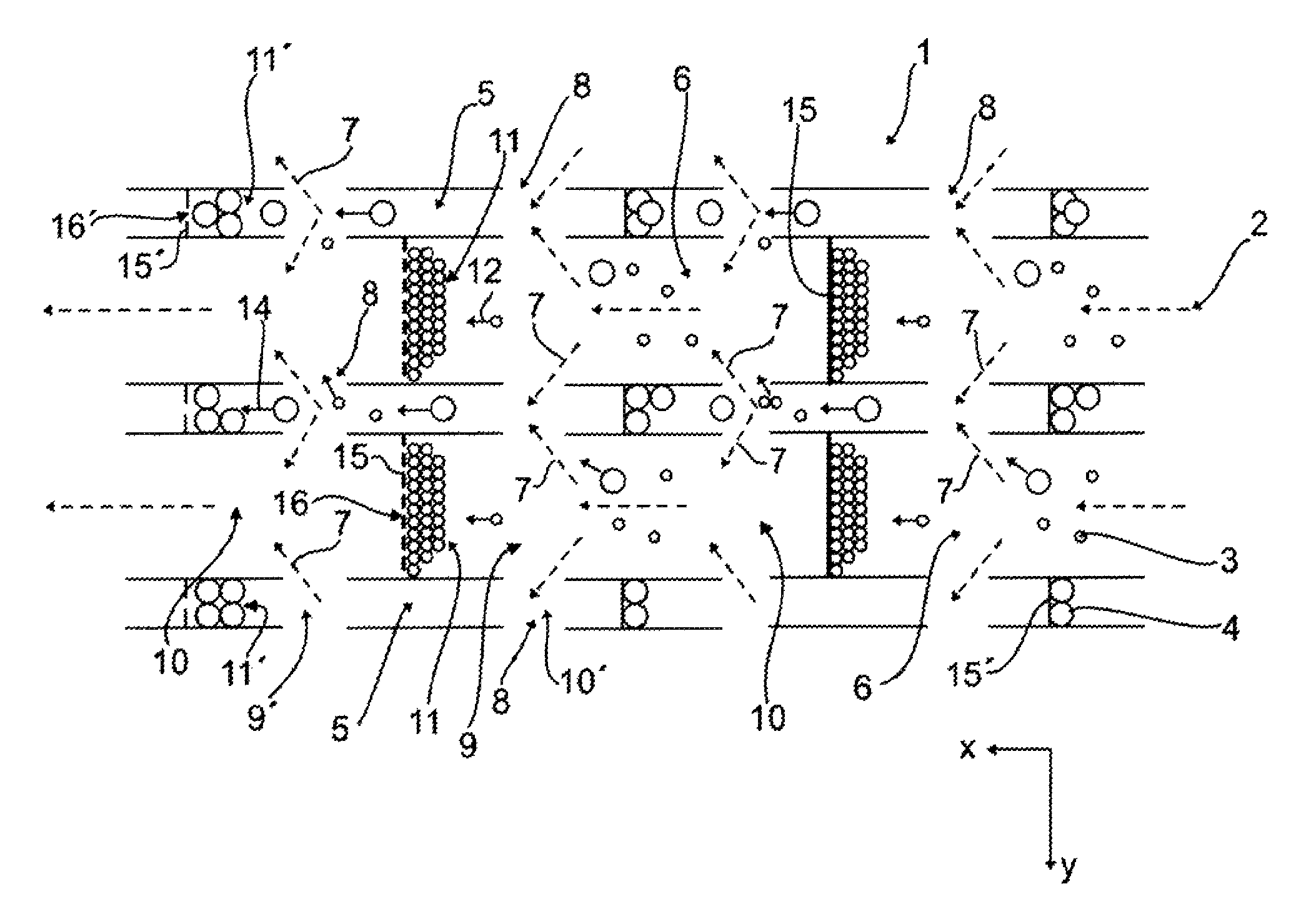
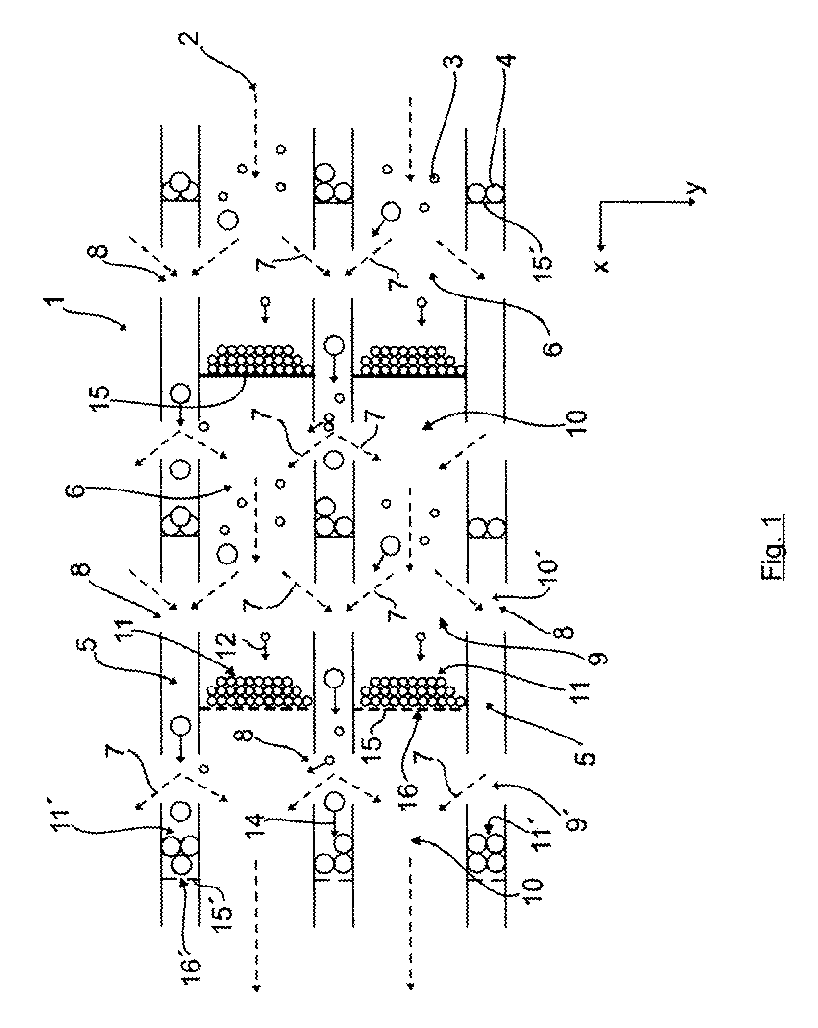
[0030]Referring now to the drawings in detail, FIG. 1 schematically shows a parallel section through at least a portion of a first embodiment of an inventive particle separator 1, and hence is quasi a plan view onto a specific portion of the particle separator 1, illustrating in principle the flow of the exhaust gas stream 2 in conjunction with the separation or removal of very fine particles 3 and large or coarse particles 4.

[0031]For the configuration with regard to the flow conditions, in particular with regard to the flow velocity and the retention time of the exhaust gas stream in various separator zones, the particle separator 1, by way of example only, has two groups of different flow regions, which here, within each of the two groups, are essentially identically embodied as high velocity flow regions 5 and low velocity flow regions 6.

[0032]In contrast to the low velocity flow regions 6, the high velocity flow regions 5 have a distinctly smaller free flow cross-sectional area...


PUM

PropertyMeasurementUnit
temperaturesaaaaaaaaaa
sizesaaaaaaaaaa

Abstract

A particle separator and method for removing particles from an exhaust gas stream of an internal combustion engine. Differing flow regions having different flow conditions are formed in the particle separator. The differing flow regions are configured such that essentially particles having different, defined sizes and / or masses are adapted to be separated out of the exhaust gas stream in the differing flow regions. The exhaust gas stream is adapted to flow through at least portions of the particle separator.

Description

BACKGROUND OF THE INVENTION[0001]The present invention relates to a particle separator for removing particles from an exhaust gas stream of an internal combustion engine. The present invention also relates to a method for removing particles from an exhaust gas stream of an internal combustion engine.[0002]During combustion in a diesel engine, and also during direct injection with a spark ignition engine, emissions of particles occur that among other reasons result due to the incomplete combustion of the fuel, and predominantly comprise carbon black. To burn this carbon black, GB 895,990 A proposes burning or treating them with NO2 as oxidizing agent instead of oxygen.[0003]It is furthermore known from U.S. Pat. No. 4,902,487 to separate off carbon particles at a filter, and to subsequently oxidize the particles with NO2. To produce the NO2, pursuant to DE 28 320 02, for example, the NO contained in the exhaust gas stream of the internal combustion engine can be oxidized on a platinu...

Claims


Application Information

Patent Timeline
Patent Type & Authority Patents(United States)
IPC IPC(8): B01D45/00B01D53/94B01D53/92B01D46/00
CPCB01D45/06B01D45/08F01N3/037F01N13/009F01N2570/10Y02T10/20Y02T10/12
Inventor DORING, ANDREAS
Owner MAN TRUCK & BUS AG
Why Eureka
Try Eureka