Bidirectional optical module and optical time domain reflectometer

a bidirectional optical module and reflectometer technology, applied in the direction of optical elements, testing fibre optic/optical waveguide devices, instruments, etc., can solve the problems of increasing coupling losses, adverse effects on the bidirectional optical module, and increasing manufacturing costs, so as to achieve high sensitivity, high optical power, and the effect of miniaturization

Active Publication Date: 2010-12-14
YOKOGAWA ELECTRIC CORP +1
View PDF4 Cites 76 Cited by
  • Summary
  • Abstract
  • Description
  • Claims
  • Application Information

AI Technical Summary

Benefits of technology

[0017]Thus, the present invention addresses the problems described above and provides a new and improved bidirectional optical module and an OTDR that has high optical power and high sensitivity and can be miniaturized.
[0019]According to the present invention, polarization planes of light after being emitted from the plurality of light emitting elements are mutually orthogonal. Light having such polarization planes after being emitted from the light emitting elements enters the optical fiber via the non-reciprocal unit. Then, returning light from the optical fiber enters one light receiving element via the non-reciprocal unit. By orthogonalizing directions of the polarization planes of lights emitted from the plurality of light emitting elements in this manner, the optical path in the forward direction and that in the backward direction can be made different in the non-reciprocal unit so that a bidirectional optical module can be constructed with a smaller number of components.
[0020]Here, light emitted from the plurality of light emitting elements is emitted from a first port or a second port. At this point, light emitted from the first port is incident with an inclination of a predetermined angle in a positive direction with respect to an optical axis of the non-reciprocal unit, and light emitted from the second port is incident with the inclination of the predetermined angle in a negative direction with respect to the optical axis of the non-reciprocal unit. Accordingly, spacing between the light emitting element and light receiving element in a perpendicular direction with respect to the optical axis of the non-reciprocal unit can be increased.
[0023]A double refraction optical element for refracting the optical path between the light emitting element and the non-reciprocal unit may be provided. Accordingly, the distance between the light emitting element and the non-reciprocal unit can be shortened to further reduce the size of the bidirectional optical module.
[0024]Further, a multiplexing / demultiplexing filter for multiplexing lights emitted from the plurality of light emitting elements may be provided between the light emitting elements and the double refraction optical element. That is, lights emitted from two or more light emitting elements are multiplexed by the multiplexing / demultiplexing filter so that the multiplexed light can be emitted from one port. Accordingly, light of three or more wavelengths can be caused to enter the optical fiber by a simple constitution.
[0026]According to the present invention described above, a bidirectional optical module that has high optical power and high sensitivity and can be miniaturized and an OTDR can be provided.

Problems solved by technology

Thus, manufacturing costs go up and coupling losses of the components increase, affecting the bidirectional optical module 1 adversely.
Moreover, because a melting type optical fiber coupler is generally used as the multiplexing / demultiplexing couplers 20 and 30, troublesome work such as fusing work of optical fiber and accommodation of remaining-length optical fiber arises.
Thus, there is a problem that working man hours in the manufacturing process increase and miniaturization of the bidirectional optical module 1 becomes more difficult.
Further, when the bidirectional optical module 1 for OTDR of three waves or more is configured, there is a problem that the configuration of the multiplexing / demultiplexing couplers 20 and 30 becomes very complicated and manufacturing costs go up.

Method used


Image

  • Bidirectional optical module and optical time domain reflectometer
  • Bidirectional optical module and optical time domain reflectometer
  • Bidirectional optical module and optical time domain reflectometer

Examples


first embodiment

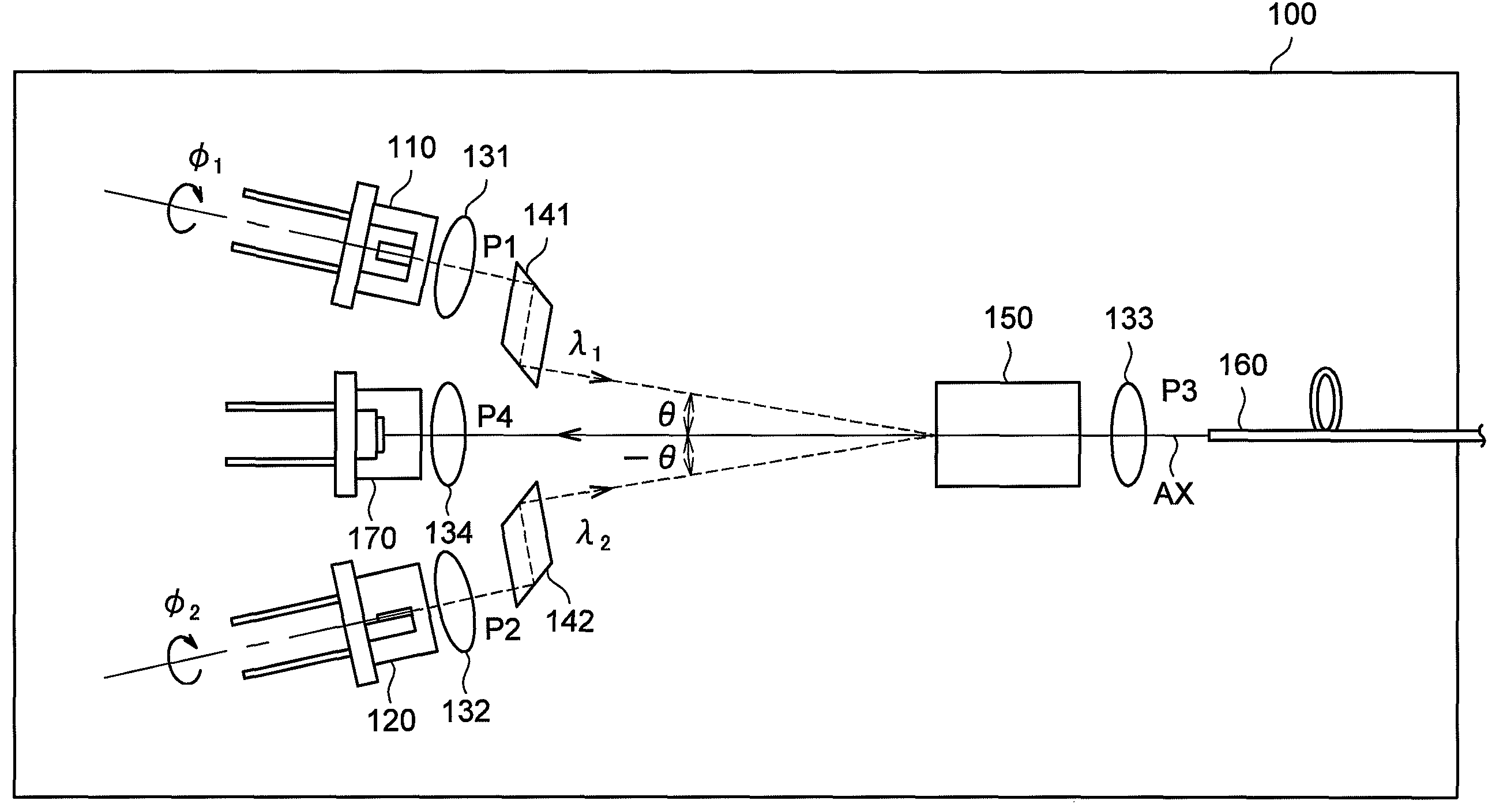
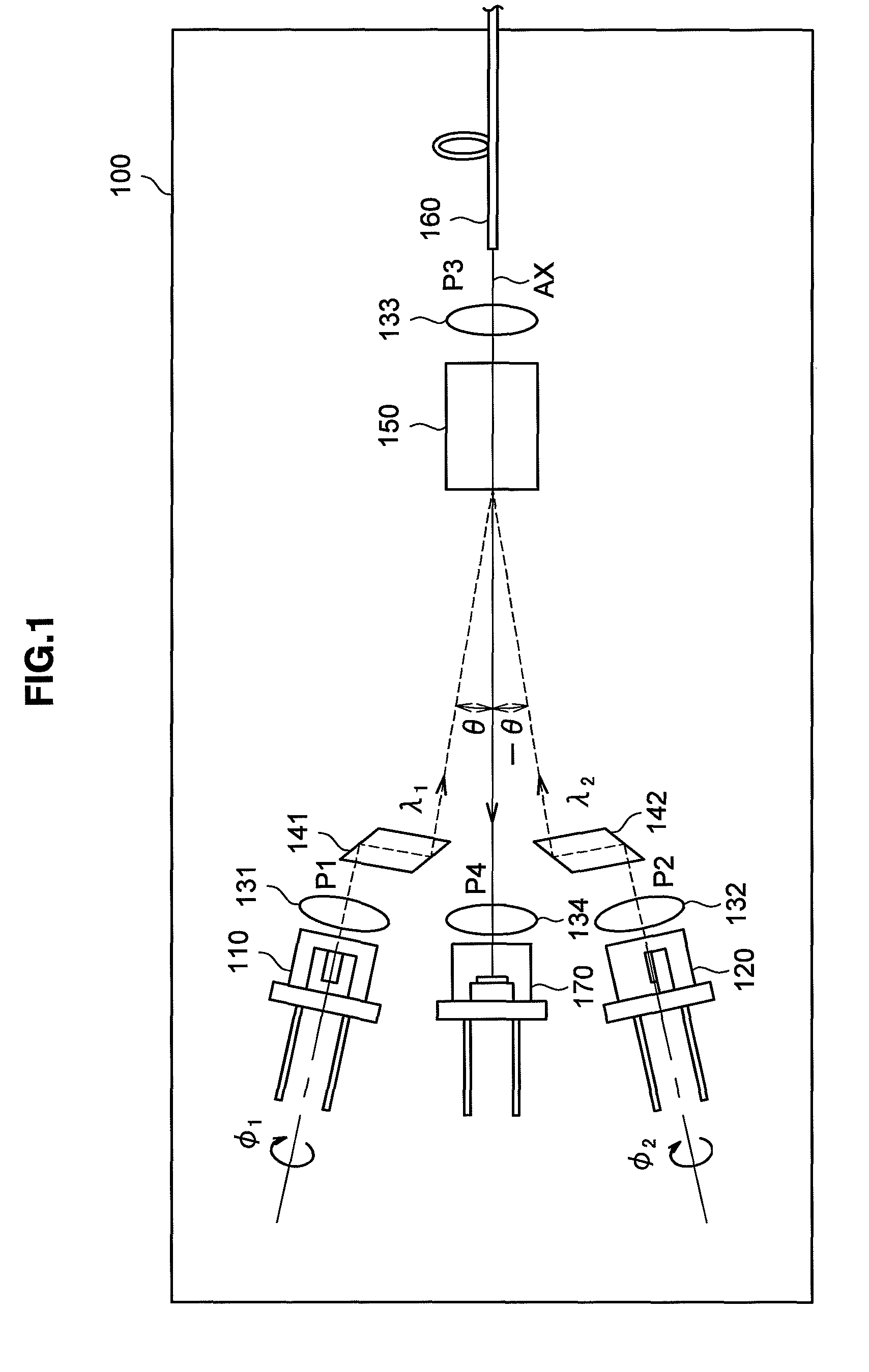
[0035]First, the configuration of a bidirectional optical module 100 according to the first embodiment of the present invention will be described based on FIG. 1. FIG. 1 is an explanatory diagram showing the configuration of the bidirectional optical module 100 according to the present embodiment.

[0036]The bidirectional optical module 100 according to the present embodiment includes, as shown in FIG. 1, light emitting elements 110 and 120 to emit light, lenses 131 and 132 to make light parallel, lenses 133 and 134 to condense light, refractive prisms 141 and 142, a non-reciprocal unit 150 to allow light to pass only in one direction, an optical fiber 160, and a light receiving element 170 to detect light. The bidirectional optical module 100 according to the present embodiment has the light emitting element 110 disposed in a first port P1, the light emitting element 120 disposed in a second port P2, the optical fiber 160 disposed in a third port P3, and the light receiving element 1...

second embodiment

[0059]Next, a bidirectional optical module 200 according to the second embodiment of the present embodiment will be described based on FIG. 3. FIG. 3 is an explanatory diagram showing the configuration of the bidirectional optical module 200 according to the present embodiment. The bidirectional optical module 200 according to the present embodiment is different, when compared with the first embodiment, in that the bidirectional optical module is provided for three wavelengths by adding a light emitting element 210. A difference from the first embodiment will mainly be described below and a detailed description of the same constitution and the same operation is omitted.

[0060]The bidirectional optical module 200 according to the present embodiment includes, as shown in FIG. 3, the light emitting elements 110, 120, and 210 to emit light, the lenses 131 and 132 and a lens 231 to make light parallel, the lenses 133 and 134 to condense light, a multiplexing / demultiplexing filter 240, the...


PUM


Abstract

A bidirectional optical module according to the present invention emits light to an optical fiber and allows returning light from the optical fiber to enter and includes a plurality of light emitting elements that emit light to enter the optical fiber, a light receiving element that receives light having exited the optical fiber, and a non-reciprocal unit for making an optical path in a forward direction from the light emitting element to the optical fiber and an optical path in a backward direction from the optical fiber to the light emitting element different. Then, polarization planes of light incident on the optical fiber after being emitted from the plurality of light emitting elements are mutually orthogonal, and the non-reciprocal unit emits returning light of light emitted from the plurality of light emitting elements from the optical fiber toward the light receiving element to one light receiving element.

Description

CROSS REFERENCES TO RELATED APPLICATIONS[0001]The present invention contains subject matter related to Japanese Patent Application JP 2007-275590 filed in the Japan Patent Office on Oct. 23, 2007, the entire contents of which being incorporated herein by reference.BACKGROUND OF THE INVENTION[0002]1. Field of the Invention[0003]The present invention relates to a bidirectional optical module and more specifically, it relates to a bidirectional optical module to be included in an OTDR used in applications such as measurement of a fracture in an optical fiber communication network.[0004]2. Description of the Related Art[0005]A measuring device such as an optical fiber sensor, which executes measurement by using light in an optical communication system or the like, includes a light source that emits light and a light receiving unit that receives the light. A measuring device utilized in maintenance, management and the like of an optical communication system includes a light source that e...

Claims


Application Information

Patent Timeline
Patent Type & Authority Patents(United States)
IPC IPC(8): G02B6/42
CPCG01M11/3127G01M11/3181G02B6/4206G02B6/4208G02B6/4246
Inventor OOTA, KATSUSHISHIBUYA, HARUOTAMURA, YASUAKISAKAI, SHUNJI
Owner YOKOGAWA ELECTRIC CORP
Why Eureka
Try Eureka