Artificial total lumbar disc for unilateral safe and simple posterior placement in the lumbar spine, and removable bifunctional screw which drives vertical sliding expansile plate expansion, and interplate widening, and angled traction spikes

a total lumbar disc and lumbar spine technology, applied in the field of posterior placement total lumbar disc, can solve the problems of limited placement, significant risk of retrograde ejaculation, and limited single-level replacemen

Inactive Publication Date: 2010-12-21
MOSKOWITZ FAMILY LLC
View PDF39 Cites 162 Cited by
  • Summary
  • Abstract
  • Description
  • Claims
  • Application Information

AI Technical Summary

Problems solved by technology

However based on the current anterior cervical prosthetic disc screw fixation methodology its implantation is periodically complicated by screw failures e.g. partial or complete screw pullouts or breaks, and in most designs it is limited to single level replacement.
Furthermore, for lumbar total artificial discs, placement is limited to only the L4 / 5 and L5 / S1 disc spaces, and not above, secondary to aortic and vena caval anatomical restraints.
Furthermore, despite the purported safety of placement of the current anterior total lumbar artificial discs, there is a significant risk of retrograde ejaculations in males, and the risk of vascular injury, which although small, is potentially catastrophic if it occurs.
Their major limitation is the lack of elasticity and shock absorption capacity.
On the other hand, their long term durability beyond ten years is not currently known.
Furthermore by so doing, the probability of recurrent herniation plummets, and subsequently the need for posterior pedicle instrumentation plummets, thereby diminishing overall spinal morbidity, expenditure, and leading to the overall improvement in the quality of life.
Presumably up to now, technology is not focusing on posterior placement of total lumbar prosthetic discs because of inadequate access to the disc space posteriorly.
The approach of posteriorly placing artificial disc cores appears to be flawed in that: 1) there is a high extrusion rate, 2) it lacks good fixation as does total prosthetic devices that are placed anteriorly, 3) it is restricted only to early symptomatically disrupted discs which have only nucleus pulposus but not annulus or endplate pathology, and 4) are contraindicated in discs with an interspace height of less than 5 mm.
The major disadvantages of anterior placement of these devices include vascular injury, blood loss, and retrograde ejaculation in males.
Their surgical removal if warranted is technically challenging and potentially fatal in extreme circumstances.

Method used


Image

  • Artificial total lumbar disc for unilateral safe and simple posterior placement in the lumbar spine, and removable bifunctional screw which drives vertical sliding expansile plate expansion, and interplate widening, and angled traction spikes
  • Artificial total lumbar disc for unilateral safe and simple posterior placement in the lumbar spine, and removable bifunctional screw which drives vertical sliding expansile plate expansion, and interplate widening, and angled traction spikes
  • Artificial total lumbar disc for unilateral safe and simple posterior placement in the lumbar spine, and removable bifunctional screw which drives vertical sliding expansile plate expansion, and interplate widening, and angled traction spikes

Examples


Embodiment Construction

The Medical Device of FIGS. 1-7

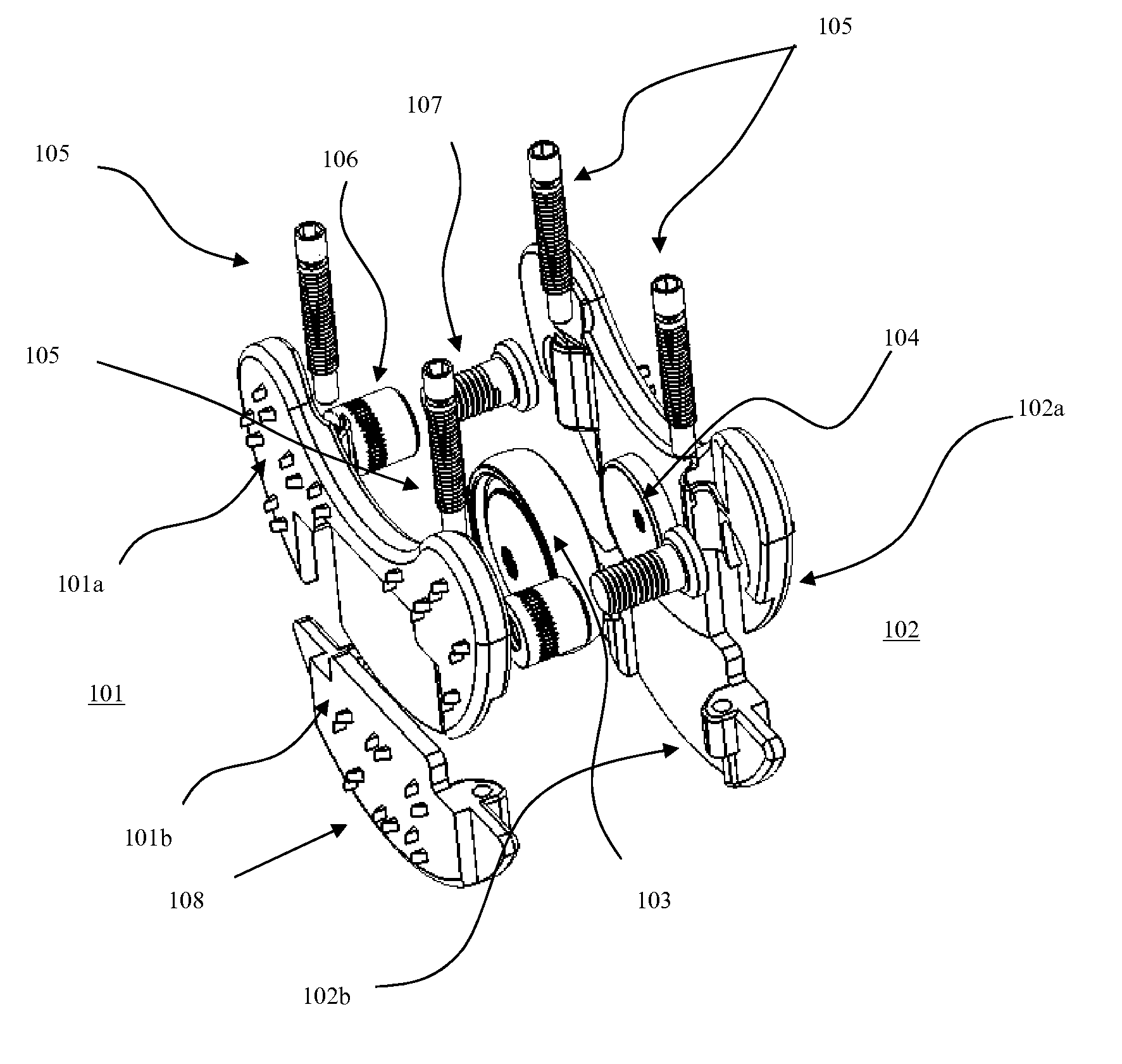
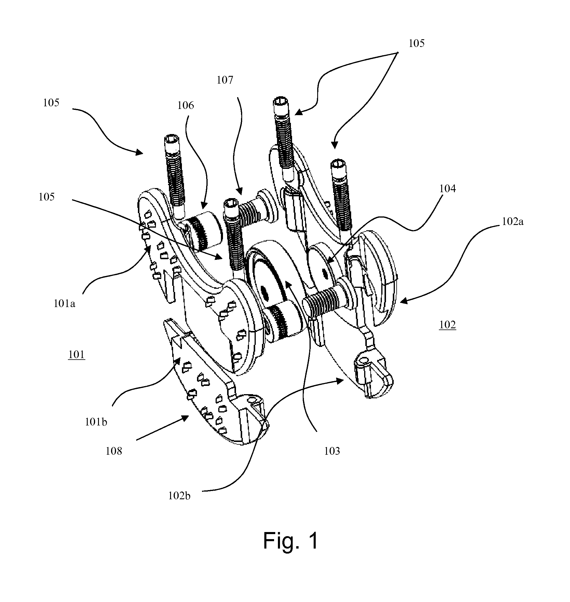
[0031]Referring now to FIGS. 1-7, the above described problems can be solved in the lumbar spine by the posterior insertion of a closed PPLTAD in the discs space after the performance of a discectomy. After insertion it is expanded in height (the anterior-posterior direction in a standing patient), and in width (disc space height in a standing patient).

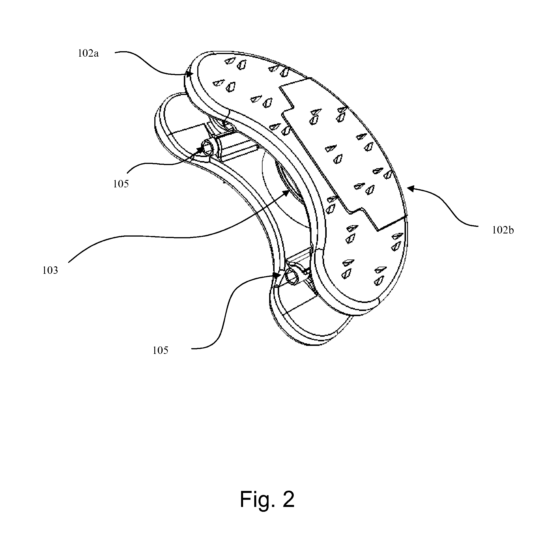
[0032]FIG. 1 illustrates an isometric exploded view of the PPLTAD. It consists of two opposing plates 101, 102 which are preferably titanium or cobalt chromium, each of which is comprised of a dorsal component 101a, 102a and ventral component 101b, 102b. Sandwiched in between the opposing plates 101, 102 is a removable ball 103 which contacts a trough 104 on the inner aspects of both opposing plates.

[0033]The mechanical crux to the PPLTAD height and width expandability are based on the interaction of a bi-functional (height / width) adjustment (BFA) screw 105 with a slotted worm nut 106, and a width adjust...


PUM


Abstract

A total artificial expansile disc and a method for posterior insertion between a pair of vertebral endplates are disclosed. The total artificial expansile disc includes at least one pair of substantially parallel plates that move apart along a first axis, in order to occupy a space defined by the vertebral endplates. In another embodiment, each of substantially parallel plates includes a first plate and a second sliding plate. An expansion device or tool is used to move the substantially parallel pair of plates apart along the first axis. A core is disposed between the pair of plates, and the core permits the vertebral endplates to move relative to one another. A ball limiter or ball extender prevents the core from being extruded from between the substantially parallel plates.

Description

[0001]This application is a Continuation-In-Part of provisional application 60 / 788,720 filed on Apr. 4, 2006, for which priority is claimed under 35 U.S.C. §120, and which claims the benefit under 35, U.S.C. §119(e) of copending applications Ser. No. 11 / 019,351, filed on Dec. 23, 2004 and Ser. No. 10 / 964,633, filed on Oct. 15, 2004; this application also claims priority under 35 U.S.C. §120 of U.S. provisional applications Nos. 60 / 578,319 filed on Jun. 10, 2004; 60 / 573,346 filed on May 24, 2004; 60 / 572,468 filed on May 20, 2004; 60 / 570,837 filed on May 14, 2004; and 60 / 570,098 filed on May 12, 2004; the entire contents of all the above identified patent applications are hereby incorporated by reference.BACKGROUND OF THE INVENTION[0002]1. Field of the Invention[0003]The present invention relates to a posterior placed total lumbar artificial disc (“PTTLAD”) without supplemental instrumentation, that uses removable bi-functional screws, sliding expansile plates, and interchangeable cor...

Claims


Application Information

Patent Timeline
Patent Type & Authority Patents(United States)
IPC IPC(8): A61F2/44
CPCA61F2/442A61F2/4611A61F2002/3055A61F2002/30556A61F2002/30579A61F2002/30663A61F2002/30841A61F2002/4622A61F2002/4627A61F2002/4628A61F2220/0025A61F2230/0015A61F2230/0071A61F2250/0006A61F2250/0009A61F2310/00023A61F2310/00029A61F2002/30133A61F2002/30242A61F2002/305A61F2002/30525A61F2002/30538
Inventor MOSKOWITZ, NATHAN C.MOSKOWITZ, MOSHEH T.GLOZMAN, DANIEL
Owner MOSKOWITZ FAMILY LLC
Why Eureka
Try Eureka