Direct exchange geothermal heating/cooling system sub-surface tubing installation with supplemental sub-surface tubing configuration

a geothermal heating/cooling system and sub-surface tubing technology, applied in the direction of domestic cooling equipment, heat pumps, lighting and heating equipment, etc., can solve the problems of large surface area, easy overstress of pit style systems, and occupy most all available yard space, so as to increase the overall system operational efficiency

Inactive Publication Date: 2010-12-28
EARTH TO AIR SYST
View PDF70 Cites 26 Cited by
  • Summary
  • Abstract
  • Description
  • Claims
  • Application Information

AI Technical Summary

Benefits of technology

[0020]Such a supplemental liquid line refrigerant transport loop in a vertically inclined borehole provides a means to take the load off a traditionally designed pit system during overstressed conditions, particularly in the cooling mode, all while requiring only as little additional surface area as a 5 to 6 inch diameter borehole. Depending on the tonnage overload during stressed conditions, the supplemental liquid refrigerant transport line should preferably be installed within a loop that is at least 80 feet deep, and preferably at least 120 feet deep, per ton of stress system overload. One of the supplemental lines in the well loop should preferably be insulated at least 25% of the way down from the top, and preferably at least 75% of the way down from the top, so as to prevent a “short-circuiting” effect of the warm liquid line being within the same borehole as the cool liquid line (whether operating in either the cooling or the heating mode).
[0021]Additionally, the empty annular space within the borehole, after the insulated liquid line loop has been installed, should be filled with a heat conductive fill material, such as a preferable Grout 111 mix. Grout 111, which is well understood by those skilled in the art, is a cementitious grout that has a very high heat conductivity rate of 1.4 BTUs / Ft. Hr. Degree F., is shrink resistant, is crack resistant, and helps to prevent potential sub-surface and above-surface contaminants from entering the ground's adjacent sub-surface strata. In most residential and light commercial applications, testing has shown that the size of the supplemental liquid refrigerant transport line should preferably vary between a ⅜ inch O.D. and a ½ inch O.D. size, with a 0.03 inch wall thickness, depending on the size of the system's compressor. Preferably a 1 ton through a 2.5 ton compressor should utilize a ⅜ inch O.D., plus or minus 20%, supplemental liquid refrigerant transport line size, and a compressor larger than 2.5 tons, up to 7.5 tons, should use a ½ inch O.D., plus or minus 20%, line size for optimal system operation in such a vertically oriented supplemental liquid line design.
[0022]In addition to being available to help relieve overstressed DX pit system designs, the addition of a supplemental vertical well liquid line loop, as a matter of standard practice, will increase overall system operational efficiencies because of the exposure of the circulating sub-surface heat exchange refrigerant to additional ground area at the more steady-state temperatures found at depths farther from the ground surface, which are not subject to the affects of widely fluctuating atmospheric temperature conditions. Generally, the ground temperature is relatively unaffected by atmospheric temperature changes at a depth of about 65.6 feet.
[0024]The common problem of vertical well type DX systems periodically becoming partially filled up with debris can be easily solved by extending the shorter vapor refrigerant transport line segment of the loop in a horizontal trench, which trench is excavated to a depth of at least one foot below the frost line in the particular geographic location, and preferably at least four below the frost line. In such an application, the extended vapor line segment installed within the mostly horizontally oriented trench should preferably be covered with at least one of powdered stone and Grout 111. Further, a perforated “soaker” hose should preferably be placed over the stone / Grout prior to backfilling, with a sealed shut distal end, and with the open end attached to at least one of the air handler's condensate drain line and a pressure water hose so as to keep the near-surface segment moist in the cooling mode of operation.
[0027]In both such design improvements, the first improvement being comprised of a vertically oriented well loop for the primary liquid refrigerant line in a DX pit system, and the second improvement being comprised of a supplemental horizontally oriented vapor heat exchange line for a short-looped vertically oriented DX well system, the use of a refrigerant with at least a 10% greater operating pressure than that of R-22, such as R-410A, would be preferable and would enhance system operational efficiencies. Field testing has shown that higher refrigerant operational pressures (than that of commonly used R-22) offset the negative impacts of operational refrigerant transport suction line pressure losses in sub-surface heat exchange DX systems as described herein, particularly in the cooling mode of system operation, where the sub-surface refrigerant transport suction line is at least one of the smaller diameter liquid refrigerant transport lines.

Problems solved by technology

Thus, a large surface area is required, which may often take up most all available yard space.
Pit style systems are easily overstressed when doors or windows are accidentally left open, when outdoor temperatures exceed design levels, or when large groups of people are entertained.
The overstressing problem is most severe in the cooling mode, as more land surface area is required to dissipate heat in a DX system than to provide heat.
While one seemingly obvious solution to an overstressed pit style system would be to increase the pit size and install additional sub-surface horizontally oriented heat transfer tubing, this poses several problems.
First, there may not be adequate available land surface area.
Second, if one supplies too much tubing for a particularly sized existing compressor and air handler unit, the design refrigerant flow and design phase change in the field can become impaired, and operational efficiencies can suffer.
(A vapor line refrigerant transport loop cannot efficiently be installed in conjunction with a pit system because a phase change from vapor to liquid in a vertically inclined vapor line presents a problem with vertical lift / head pressure of the liquid through the larger diameter of the vapor line during cooling mode operation, which cooling mode is the primary concern.)

Method used


Image

  • Direct exchange geothermal heating/cooling system sub-surface tubing installation with supplemental sub-surface tubing configuration
  • Direct exchange geothermal heating/cooling system sub-surface tubing installation with supplemental sub-surface tubing configuration
  • Direct exchange geothermal heating/cooling system sub-surface tubing installation with supplemental sub-surface tubing configuration

Examples


Embodiment Construction

[0032]The following detailed description is of the best presently contemplated mode of carrying out the invention. The description is not intended in a limiting sense, and is made solely for the purpose of illustrating the general principles of the invention. The various features and advantages of the present invention may be more readily understood with reference to the following detailed description taken in conjunction with the accompanying drawings.

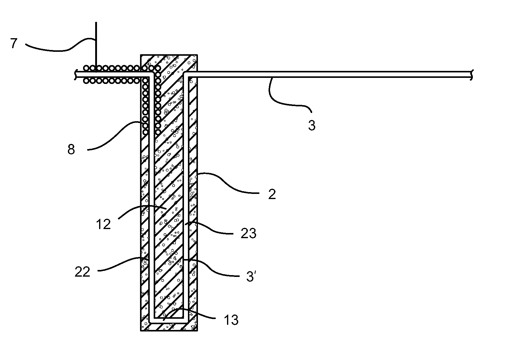
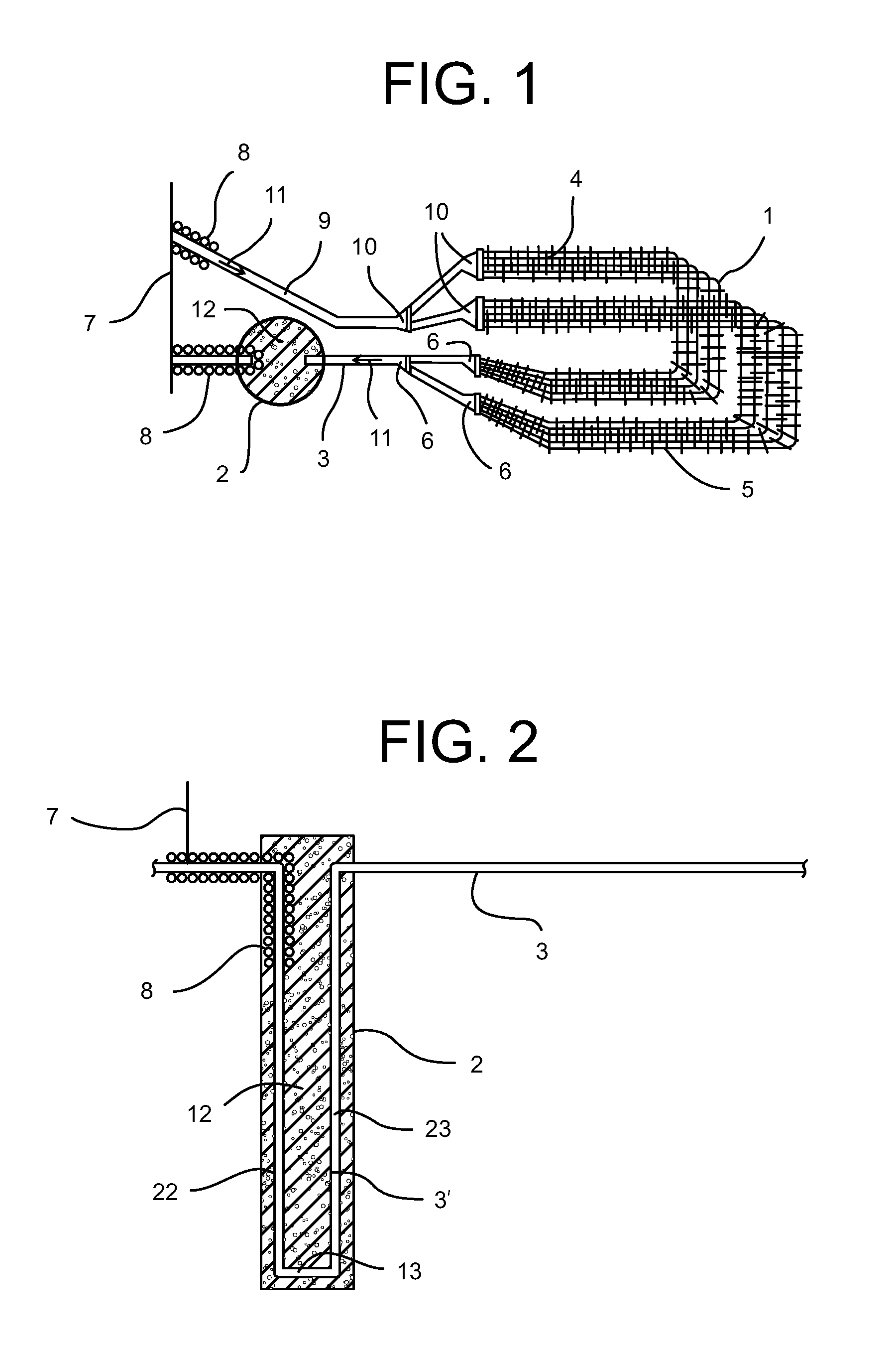
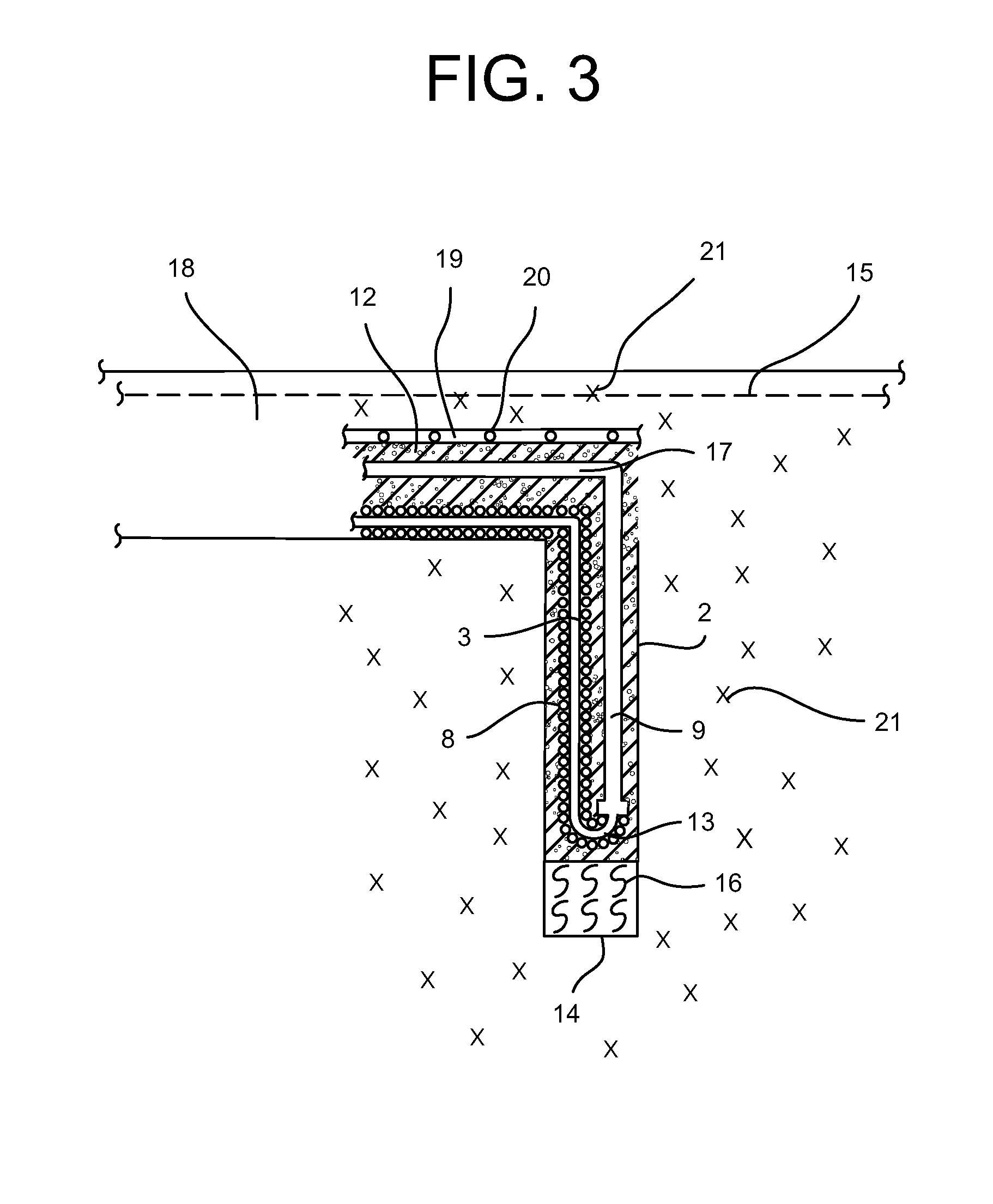
[0033]One embodiment of the invention is shown in FIG. 1, not drawn to scale, which is a top view of a horizontally inclined DX geothermal heat exchange pit system 1, in conjunction with a vertically inclined supplemental well 2 installation for the single, primary, liquid refrigerant transport line 3. Typically, depending on the size of the DX system compressor (not shown herein, as same is well understood by those skilled in the art) the primary liquid line 3 is a three-eighth inch O.D, plus or minus 20%, for a one to two and one-ha...


PUM


Abstract

A sub-surface tubing arrangement for use in a direct exchange (DX) geothermal heating / cooling system includes a primary sub-surface liquid refrigerant transport line, a primary sub-surface vapor refrigerant transport line, at least one sub-surface heat exchange refrigerant transport line functionally connecting the primary sub-surface liquid refrigerant transport line to the primary sub-surface vapor refrigerant transport line, and either vertical or horizontal supplemental sub-surface refrigerant line connected to one of the primary sub-surface liquid or vapor refrigerant transport lines.

Description

CROSS-REFERENCES TO RELATED APPLICATIONS[0001]This application is a Continuation-In-Part application which claims benefit of U.S. patent application Ser. No. 10 / 874,018 filed Jun. 22, 2004, now U.S. Pat. No. 7,146,823, entitled “Horizontal and Vertical Direct Exchange Heating / Cooling System Sub-Surface Tubing Installation Means” which is hereby incorporated by reference.[0002]A portion of the disclosure of this patent document contains material that is subject to copyright protection. The copyright owner has no objection to the facsimile reproduction by anyone of the patent document or the patent disclosure, as it appears in the U.S. Patent and Trademark Office patent file or records, but otherwise reserves all copyright rights whatsoever.STATEMENT REGARDING FEDERALLY SPONSORED RESEARCH OR DEVELOPMENT[0003]Not ApplicableREFERENCE TO SEQUENCE LISTING OR COMPUTER PROGRAM LISTING APPENDIX[0004]Not ApplicableBACKGROUND OF THE INVENTION[0005]The present invention relates to a geothermal ...

Claims


Application Information

Patent Timeline
Patent Type & Authority Patents(United States)
IPC IPC(8): F25D23/12
CPCF24J3/081F25B30/06F25B2500/01Y02E10/12F24T10/10Y02E10/10
Inventor WIGGS, B. RYLAND
Owner EARTH TO AIR SYST
Why Eureka
Try Eureka