
Method of joining metals to ceramic matrix composites

a ceramic matrix and composite material technology, applied in the direction of paper/cardboard containers, soldering devices, manufacturing tools, etc., can solve the problems of limited commercial application and difficulty in reliably connecting these two materials, and achieve the effect of high strength bonding, convenient metal bonding, and high strength

Active Publication Date: 2010-12-28
UNIV OF DAYTON
View PDF45 Cites 16 Cited by
  • Summary
  • Abstract
  • Description
  • Claims
  • Application Information

AI Technical Summary

Benefits of technology

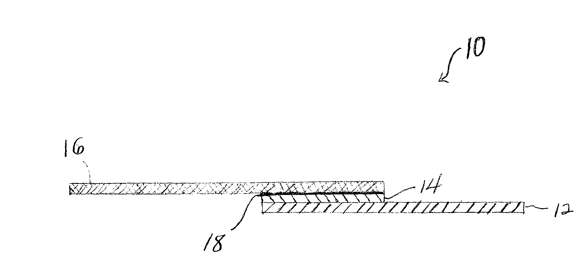
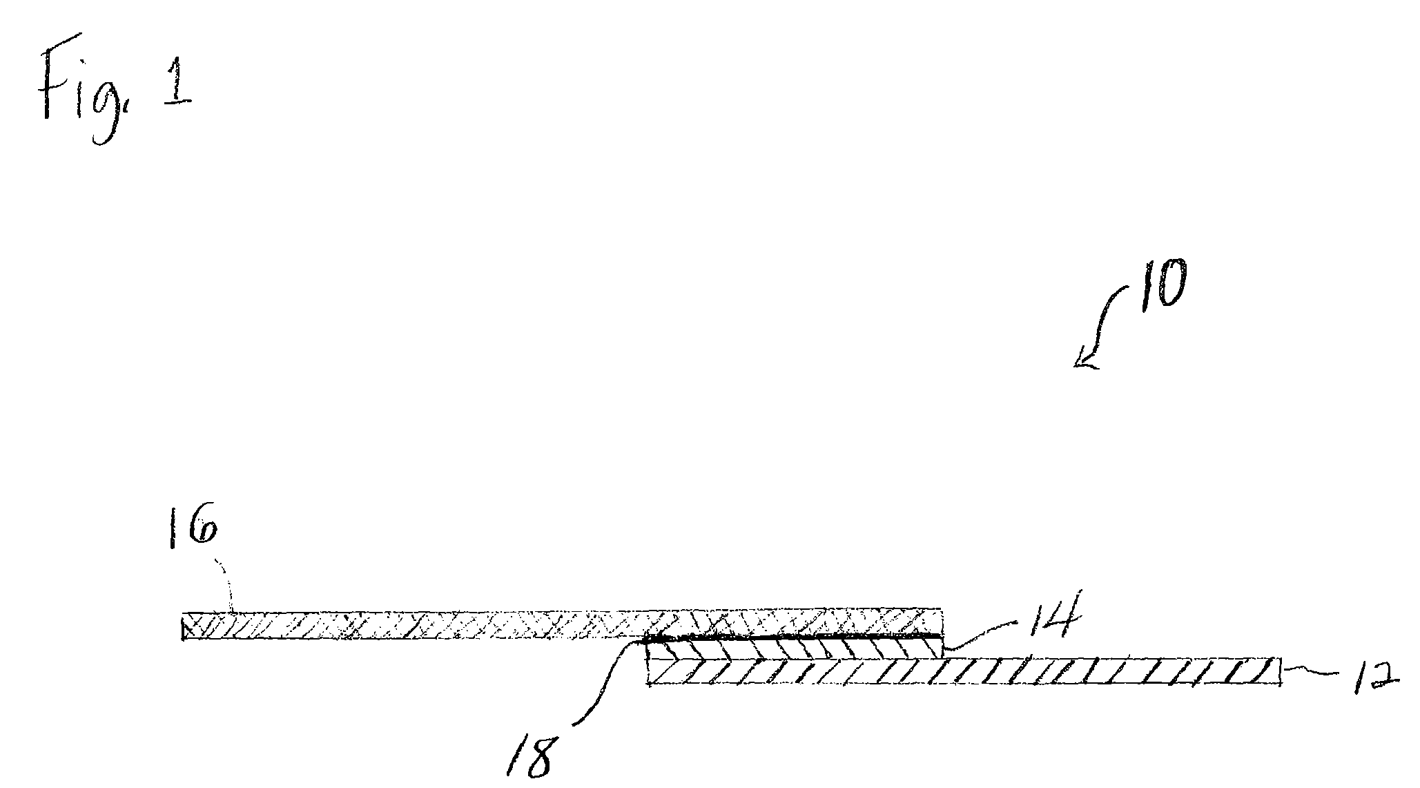
"The present invention provides a method for joining metals to ceramic materials, such as ceramic matrix composites. This is achieved by using an interlayer that facilitates bonding of the metal to the ceramic material. The resulting joined composite is able to withstand higher operating temperature environments than with the use of metal alone. The method involves bonding the metal to a compliant interlayer, which is then bonded to the ceramic material using brazing. The resulting joined metal / ceramic composite exhibits a high operating temperature."

Problems solved by technology

For example, a commercially available superalloy such as Inconel 718® has a CTE of about 14.5×10⁻⁶ cm / cm / ° C. from room temperature to about 600° C., while a SiC / SiC composite has a CTE of about 4×10⁻⁶ cm / cm / ° C. from room temperature to about 600° C. Accordingly, it has been difficult to reliably connect these two classes of materials, which has limited their commercial application.

Method used


Image

  • Method of joining metals to ceramic matrix composites
  • Method of joining metals to ceramic matrix composites
  • Method of joining metals to ceramic matrix composites

Examples


example 1

[0032]A machined bar of Inconel 718 and a 0.007 inch thick piece of Kovar (interlayer) were laser welded together to achieve a fully welded interlayer / metal structure. By “fully” welded, it is meant that multiple laser weld beads were used, in this instance, about 30. The quality of the welds was good.

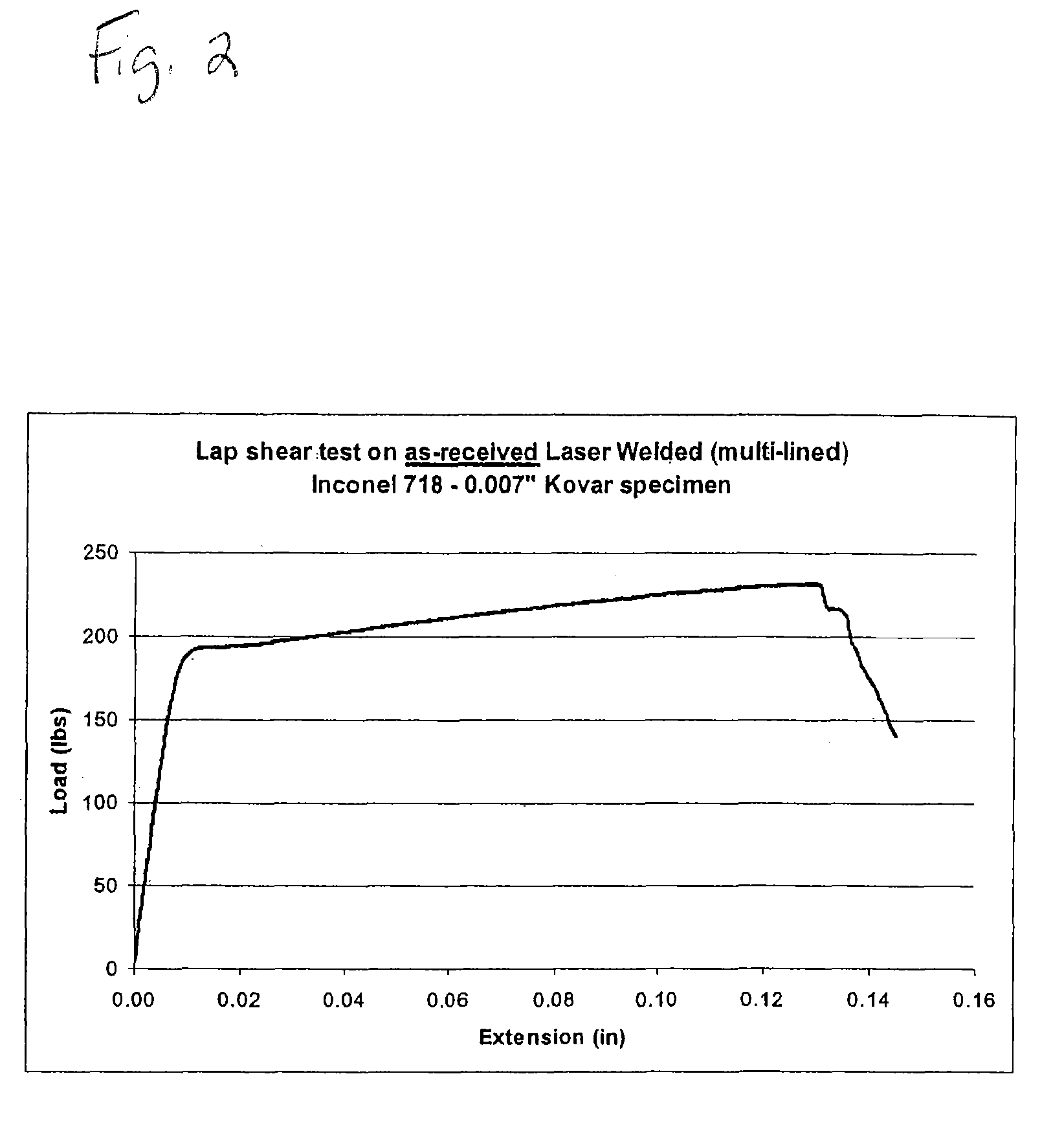
[0033]In addition, 4-line welded Inconel 718 / Kovar test specimens were also fabricated. Tensile lap shear mechanical tests were performed on laser welded Inconel 718 / 0.007″ thick Kovar specimens. The results obtained on 4-line laser welded specimens are shown in FIG. 2. The results are positive in that the tensile lap shear specimens failed only via the actual yielding of the Kovar strip material without any indication of failure in the laser weld itself. Overall, the data demonstrates that the Kovar yielded before the failure of the welds, demonstrating that the welds are inherently stronger than the Kovar.

example 2

[0034]A SiC / SiC composite was joined to a laser welded Inconel 718 / Kovar subassembly using various braze materials including Incuro, Nioro, Nioro ABA, and Ticuni (manufactured by Morgan Advanced Ceramics / Wesgo, Hayward, Calif.). Several of the resulting joined components were tensile lap shear tested. The tensile lap shear test results shown in FIG. 3 were based on test specimen IN-4 which comprised an Inconel 718-laser welded Kovar / Incuro braze / SiC—SiC composite. The results showed that the resulting bond was very strong as it failed only after the application of about 750 pounds of load which corresponds to a bond strength of about 4250 psi.

[0035]These results demonstrate that the method of the present invention provides high strength joints between a superalloy having a high coefficient of thermal expansion (such as Inconel 718) and ceramic-based SiC—SiC composites having a low coefficient of thermal expansion.


PUM

PropertyMeasurementUnit
temperatureaaaaaaaaaa
thickaaaaaaaaaa

Abstract

A method of joining metals to a ceramic material such as a ceramic matrix composite is provided which utilizes a compliant interlayer having a coefficient of thermal expansion between the coefficient of thermal expansion of the metal and that of the ceramic matrix composite. The compliant interlayer is bonded to the metal, and the ceramic matrix composite is then bonded to the bonded interlayer / metal. The method results in a high strength joint between a metal having a high coefficient of thermal expansion and a ceramic material having a low coefficient of thermal expansion.

Description

CROSS-REFERENCE TO RELATED APPLICATIONS[0001]This application claims the benefit of U.S. Provisional Application No. 60 / 915,289, filed May 1, 2007, entitled METHOD OF JOINING METALS TO CERAMIC MATRIX COMPOSITES AND OTHER CERAMIC MATERIALS. The entire contents of said application are hereby incorporated by reference.STATEMENT REGARDING FEDERALLY SPONSORED RESEARCH OR DEVELOPMENT[0002]This invention was made with government support under Contract No. CCRP 2005-03 awarded by the Ohio Aerospace Institute. The government has certain rights in the invention.BACKGROUND OF THE INVENTION[0003]The present invention is directed to a method of joining metals to ceramic matrix composites, and more particularly, to a method which provides a high strength bond between a metal such as a superalloy and a ceramic matrix composite or other ceramic material.[0004]Ceramic matrix composites and other ceramic materials are contemplated for use in a number of industries as they provide high operating tempe...

Claims


Application Information

Patent Timeline
Patent Type & Authority Patents(United States)
IPC IPC(8): B23K31/02
CPCB32B7/04C04B37/026C04B2237/123Y10T156/10C04B2237/38C04B2237/405C04B2237/708C04B2237/365C04B2237/82
Inventor KRAMER, DANIEL P.
Owner UNIV OF DAYTON
Learn More