Thrust generating apparatus

a technology of thrust generator and thrust generator, which is applied in the direction of vertical landing/take-off aircraft, flying saucers, aircraft navigation control, etc., to achieve the effect of convenient production, minimising surface area, and minimising drag

Active Publication Date: 2010-12-28
AESIR
View PDF42 Cites 24 Cited by
  • Summary
  • Abstract
  • Description
  • Claims
  • Application Information

AI Technical Summary

Benefits of technology

[0009]The curve of the surface, in the downstream direction of flow, is preferably designed to maintain the jet in its bistable state, when the arrangement is operating at full power, thereby minimising the surface area over which the jet must flow and consequently minimising drag.
[0010]The aforementioned surface is preferably dome-shaped. It will normally have a smooth continuous surface but in some variations, a peripheral edge of the dome may be segmented so that the curve at the centre of each segment is slightly different to the curve at joins between the segments. An advantage of a segmented arrangement is that it can conveniently be made using a ribbed frame with lightweight panels between the ribs. It also permits the downstream edge of each segment to be straight, this facilitating attachment of a control flap if required.

Problems solved by technology

Each of these known proposals either fails to discuss the precise curvature of the aerofoil surface or assumes that conventional practices associated with jet flow over a surface curved in a single plane will equally apply for surfaces that have double convex curvature.

Method used


Image

  • Thrust generating apparatus
  • Thrust generating apparatus
  • Thrust generating apparatus

Examples


Embodiment Construction

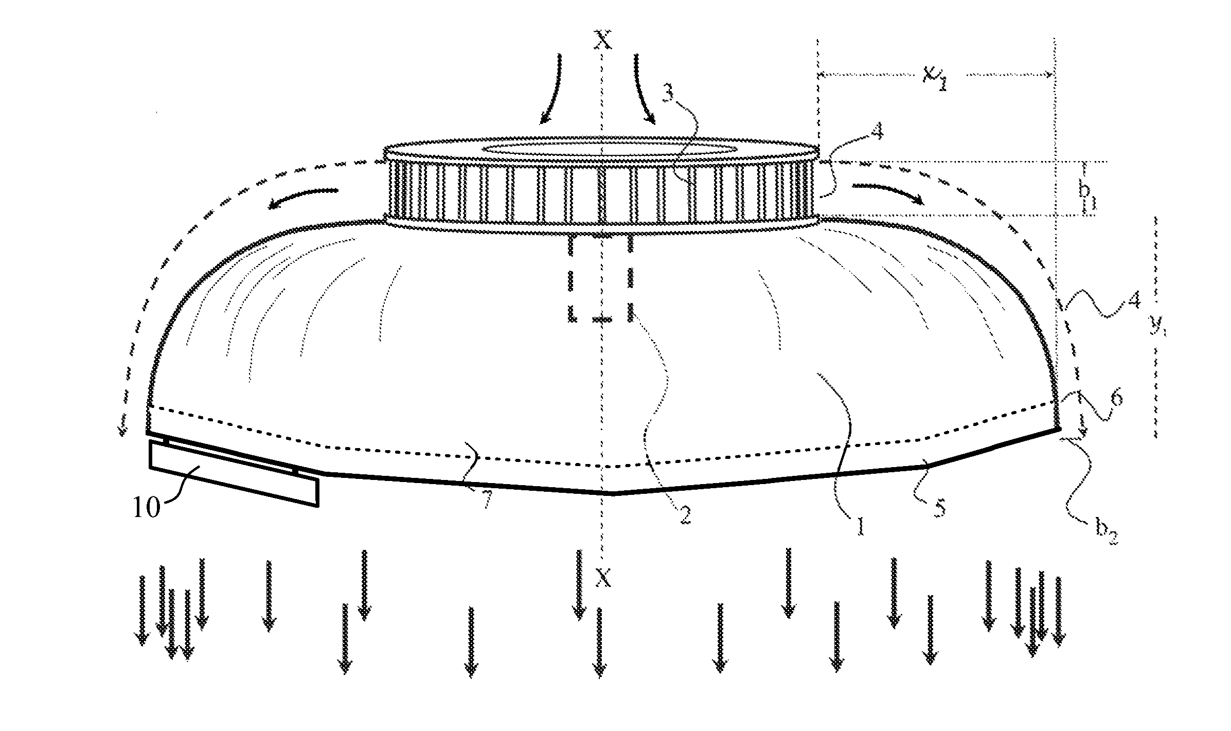
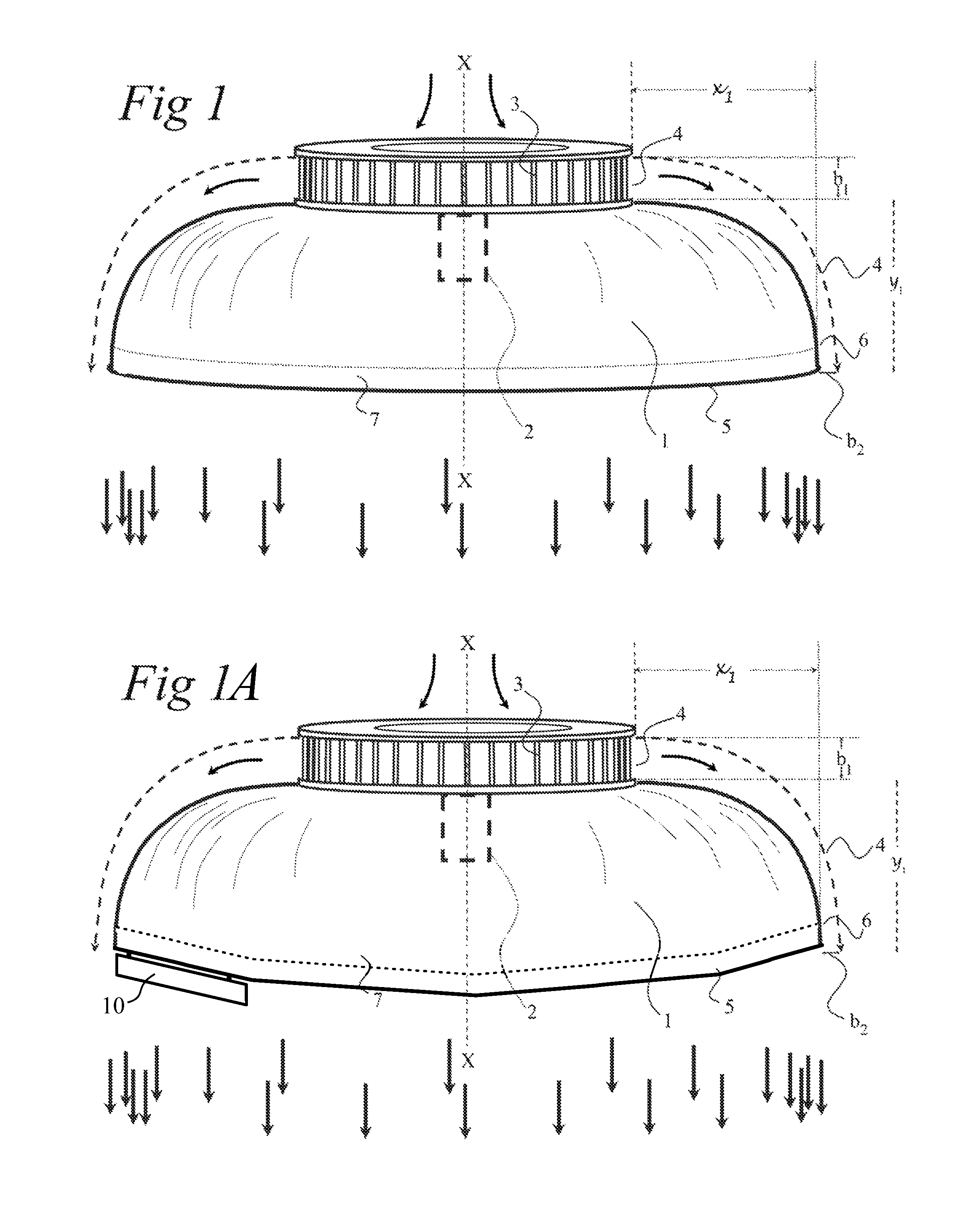
[0018]Referring to FIGS. 1, the illustrated aircraft comprises a dome-shaped canopy 1 supporting an engine 2 which in this particular embodiment is an electric motor. The motor 2 drives a radial fan 3 which propels air radially from a circular outlet slot 4 of height b1. The resulting radially flowing jet of air flows over the canopy 1 and is kept in contact with it by the Coanda effect until it reaches a bottom edge 5 where it becomes detached, forming a near-vertical annular jet. The downward momentum of this jet results in an equal upward momentum transferred to the aircraft.

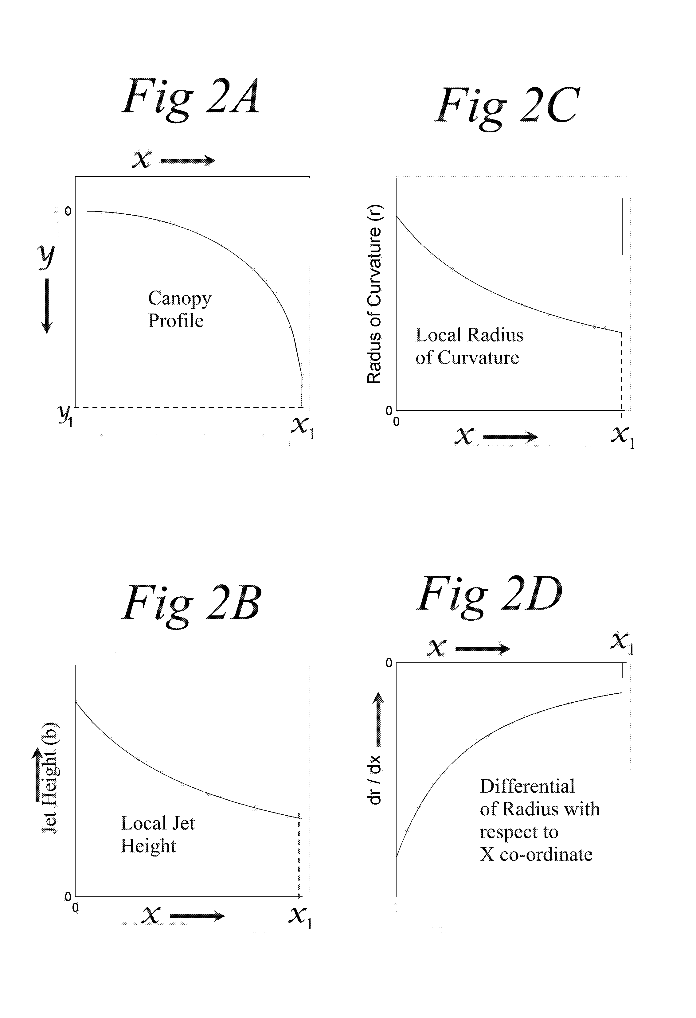
[0019]FIG. 2A shows the precise curvature of the canopy, in the direction of flow of the jet, between the outlet slot 4, and a point 6, close to, but separated from, the peripheral edge 5. A cylindrical part 7 of the canopy surface between the edge 5 and point 6 is straight (in the direction of flow). This ensures that pressures are equalised on each side of the canopy surface where the jet leaves the edge 5,...


PUM


Abstract

There have been past proposals for air vehicles employing the Coanda effect. In these proposals, a jet of fluid, usually air, is made to flow radially outwardly over 5 a dome-shaped canopy to create lift. A cross-section through the canopy is curved to follow a segment of a circle or it may have a radius of curvature that increases in the direction of flow. In the invention, the radius (r) of the canopy curve decreases towards the downstream direction (x) in a way that is related to the decrease in the width of 10 the jet as it flows over the surface. This means that the radius of curvature decreases (instead of increasing) towards the downstream direction with the rate of decrease being progressively less rapid towards the downstream direction.

Description

FIELD OF THE INVENTION[0001]This invention relates to apparatus which uses the Coanda Effect to divert a flow of fluid thereby producing a desired thrust.BACKGROUND OF THE INVENTION[0002]The Coanda effect is a phenomenon which tends to keep a jet of fluid attached to a surface over which it flows. It is discussed in a paper by Gregory-Smith entitled “The Discharge from a thin slot over a surface of convex curvature” (Int. J. Mech. Sci. Vol 24 No. 6 pp 329-339). This paper reports on an experimental study to determine the minimum radius r which the jet will follow without breaking away from it.[0003]The results of the above experiments show that for any given P0 / Pa ratio (where P0 is the total pressure and Pa is the ambient pressure) there is a value of b / r (where b is the jet width) below which the jet will be attached to the curved surface.[0004]Above this value there is a range of b / r values where the jet is bistable in the sense that, on start-up, the jet will separate from the c...

Claims


Application Information

Patent Timeline
Patent Type & Authority Patents(United States)
IPC IPC(8): B64C29/00B64C39/06
CPCB64C39/064B64C29/0025B64C39/001F04D29/441
Inventor HATTON, GEOFFREY
Owner AESIR
Why Eureka
Try Eureka