
Microresonator

a micro-resonator and resonant element technology, applied in the field of micro-resonators, can solve the problems of forming a resonant element having a polycrystalline structure, a large number of steps, and a large number of steps, and achieve the effect of simple method

Active Publication Date: 2010-12-28
STMICROELECTRONICS (CROLLES 2) SAS +1
View PDF10 Cites 0 Cited by
  • Summary
  • Abstract
  • Description
  • Claims
  • Application Information

AI Technical Summary

Benefits of technology

[0014]An object of the present invention is to provide a simple method for manufacturing a microresonator.
[0015]Another object of the present invention is to provide a microresonator structure, the resonant element of which has a good mechanical hold.
[0017]Another object of the present invention is to provide such a microresonator, the lateral motions of which are accurately detected.

Problems solved by technology

This method is complex and comprises a great number of steps.
Apart from its complexity, the previously-described method has the disadvantage of forming a resonant element having a polycrystalline structure.
The polycrystalline structure of the resonant element is a disadvantage since this causes mechanical weaknesses.

Method used


Image

  • Microresonator
  • Microresonator
  • Microresonator

Examples


Embodiment Construction

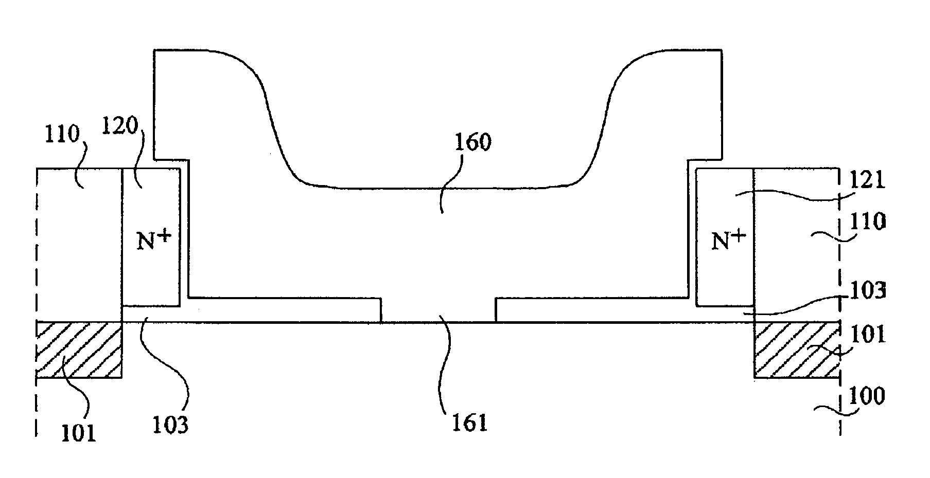
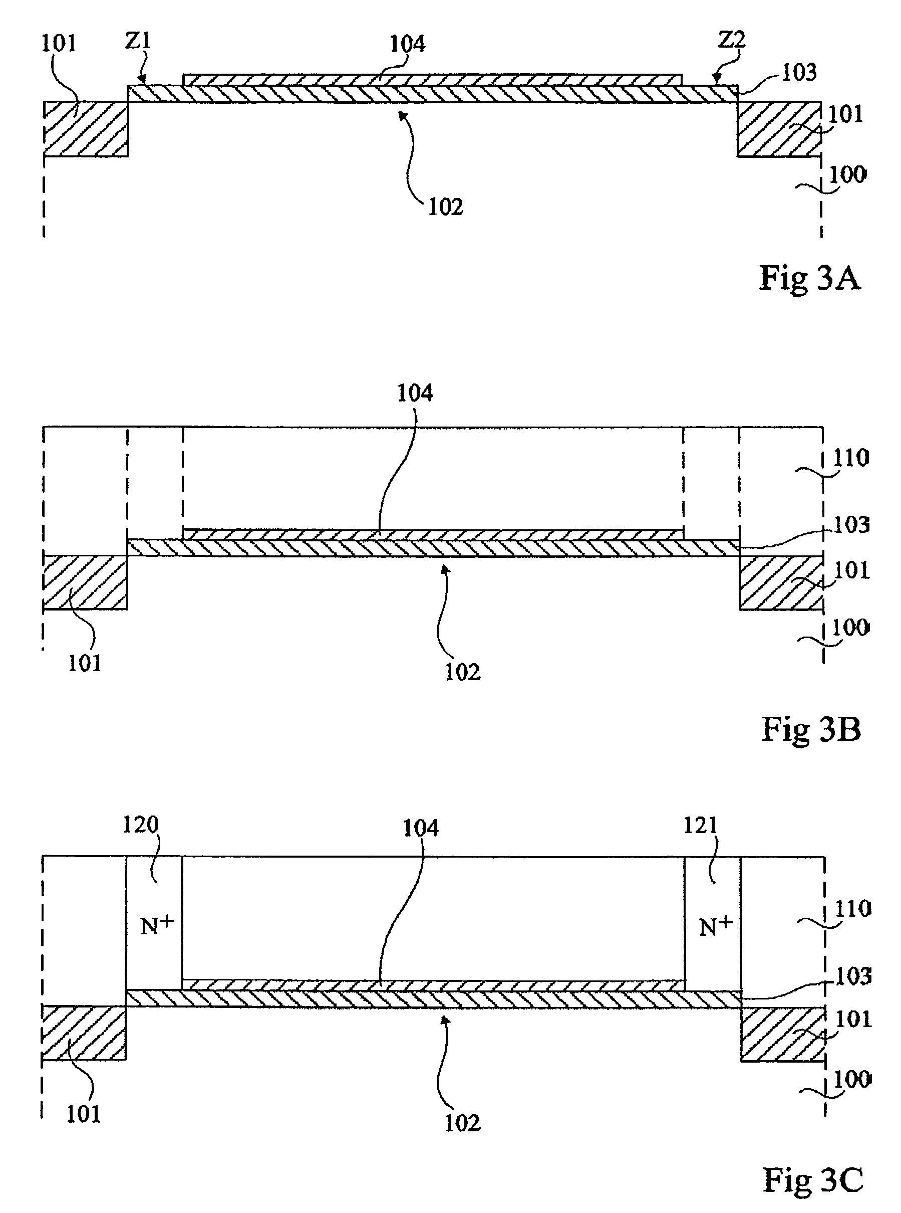
[0033]For clarity, the same elements have been designated with the same reference numerals in the different drawings and, further, as usual in the representation of integrated circuits, the various drawings are not to scale.

[0034]The method of the present invention is described hereafter in relation with FIGS. 3A to 3H.

[0035]In an initial step, illustrated in FIG. 3A, an insulating layer 101 surrounding an upper portion 102 of substrate 100 is formed in the surface of a substrate 100. Substrate 100 for example is single-crystal silicon and insulating area 101 is a trench filled with silicon oxide.

[0036]A silicon-germanium portion 103 is then grown by selective epitaxy above substrate portion 102. This epitaxial growth is conventionally performed according to a vapor phase deposition performed from a mixture of dichlorosilane and germane. The deposition method is selective to avoid growing silicon-germanium above insulating area 101.

[0037]An insulating layer portion 104 is then forme...


PUM


Abstract

A microresonator comprising a single-crystal silicon resonant element and at least one activation electrode placed close to the resonant element, in which the resonant element is placed in an opening of a semiconductor layer covering a substrate, the activation electrode being formed in the semiconductor layer and being level at the opening.

Description

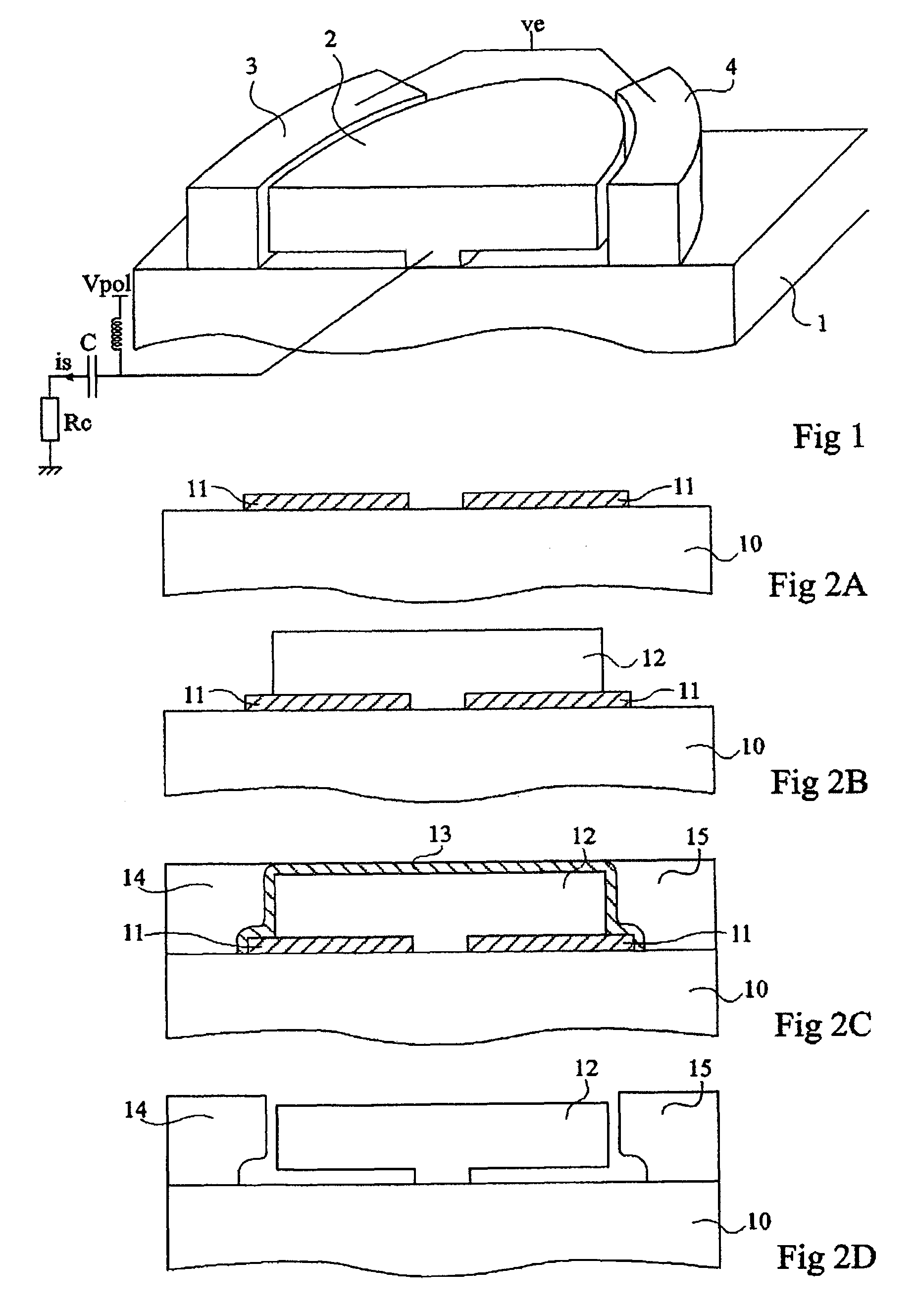
CROSS REFERENCE TO RELATED APPLICATIONS[0001]This application is a continuation of prior application Ser. No. 11 / 888,245, filed Jul. 27, 2007 entitled “Microresonator” which application is a U.S. National Stage filing of International application Ser. No. PCT / FR2006 / 050078, filed on Jan. 31, 2006, entitled “Microresonator” which application claims the priority benefit of French patent application number 05 / 50276, filed on Jan. 31, 2005, entitled “entitled “Microresonator”” which applications are hereby incorporated by reference to the maximum extent allowable by law.BACKGROUND OF THE INVENTION[0002]1. Field of the Invention[0003]The present invention relates to a microresonator.[0004]2. Discussion of the Related Art[0005]FIG. 1 is a perspective view of a known microresonator. This microresonator is described in patent WO-02 / 17482 entitled “Micromechanical resonator device and micromechanical device utilizing same”. This microresonator is formed above a substrate 1. It comprises a “m...

Claims


Application Information

Patent Timeline
Patent Type & Authority Patents(United States)
IPC IPC(8): H01L21/00H02N2/00
CPCH03H3/0072H03H9/2405H03H2009/02496
Inventor ABELE, NICOLASANCEY, PASCALTALBOT, ALEXANDRESEGUENI, KARIMBOUCHE, GUILLAUMESKOTNICKI, THOMASMONFRAY, STEPHANECASSET, FABRICE
Owner STMICROELECTRONICS (CROLLES 2) SAS
Learn More