
Magnetic levitation system

a technology of magnetic levitation and magnetic field, which is applied in the direction of magnetic bearings, magnetic holding devices, relays, etc., can solve the problem that the application of diamagnetic materials at room temperature is still scar

Active Publication Date: 2010-12-28
ETH ZZURICH
View PDF11 Cites 19 Cited by
  • Summary
  • Abstract
  • Description
  • Claims
  • Application Information

AI Technical Summary

Problems solved by technology

While the use of superconductors for magnetic levitation is already a common practice, applications of diamagnetic materials at room temperature are still scarce.

Method used


Image

  • Magnetic levitation system
  • Magnetic levitation system
  • Magnetic levitation system

Examples


Embodiment Construction

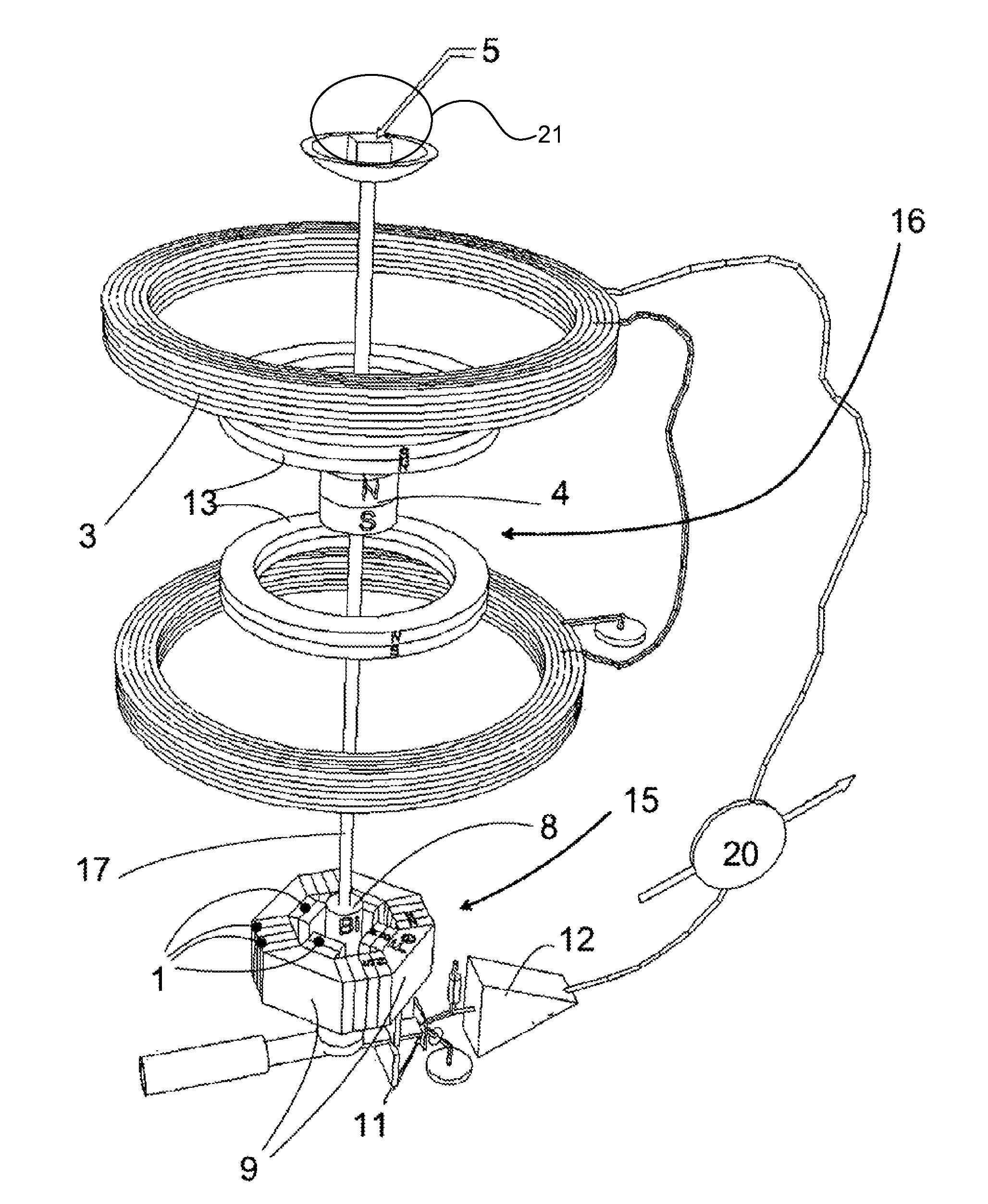
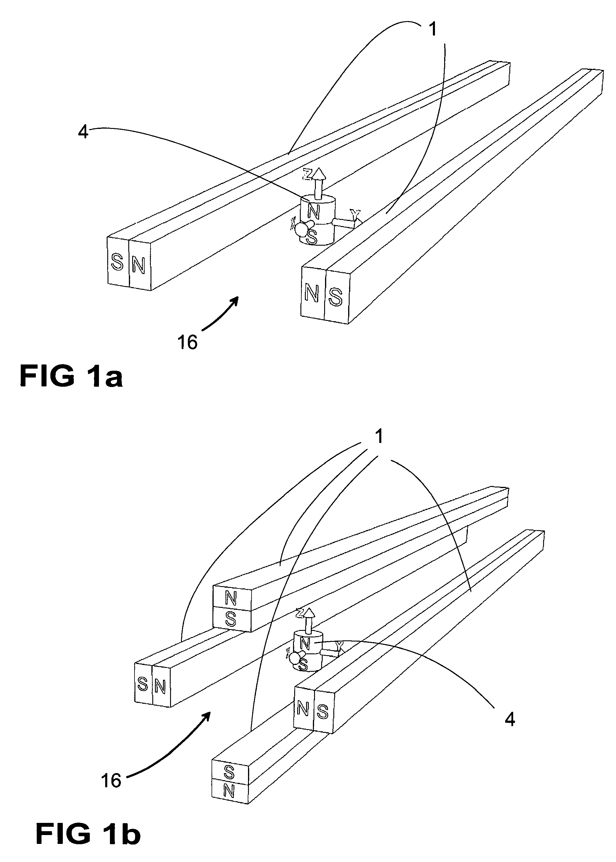
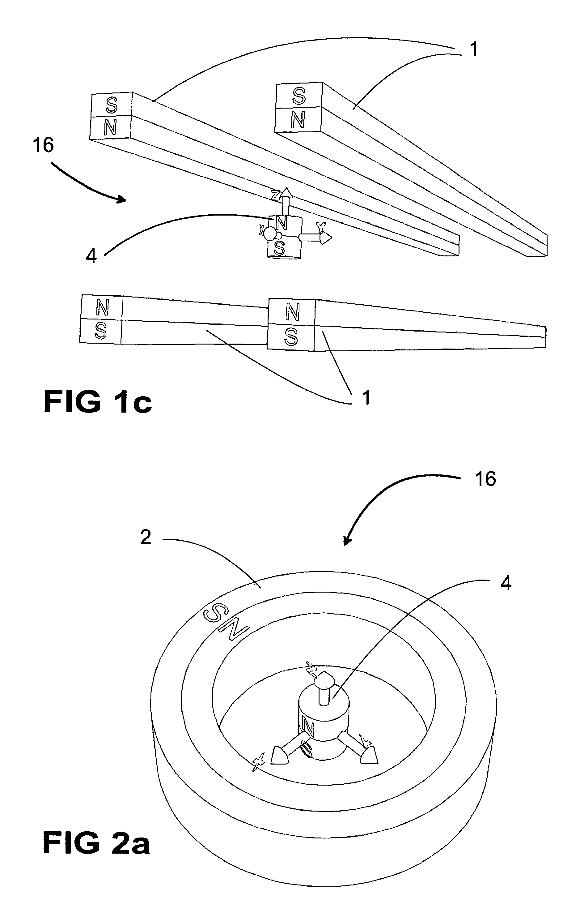
[0043]FIGS. 1a, 1b, 1c, 2a, 2b, 2c, 3a, and 3b are showing different embodiments of a supporting-field generator 16 with permanent magnets 1, 2, 6, 13 or with anti-Helmholtz coils 3, 14. In each embodiment a dipole magnet 4 is supported by a magnetic quadrupole field, called supporting field.

[0044]FIGS. 5a, 5b, 5c, 6a, 6b, 7a, 7b, 7c, 7d and 7e are showing different embodiments of a stabilizing field generator 15 comprising permanent magnets 1, 2, 13. The stabilizing field generator 15 generates a magnetic field, called stabilizing field, acting on a diamagnetic element 8.

[0045]The following addresses how a quadrupole field can be approximated with permanent magnets. The simplest way to accomplish a two-dimensional quadrupole field is by utilizing two long bars 1 of rectangular cross section magnetized perpendicularly to their longitudinal axes. The two bars 1 are mounted with axes parallel and equal poles face to face, see FIG. 1a. FIGS. 1b and 1c are showing alternative configurat...


PUM


Abstract

A magnetic levitation system for supporting an object against gravity by a supporting force includes a permanent-magnet dipole aligned in a vertical position and coupled to the object, a supporting-field generator and a stabilization system. The supporting-field generator generates a supporting force on the permanent-magnet dipole via a supporting field. The supporting field is a two-dimensional or three-dimensional magnetic quadrupole field so that the supporting force is independent of a position of the dipole. The stabilization system constrains the dipole against movements in at least one horizontal direction, and includes a diamagnetic element coupled to the dipole and arranged below the dipole, and a stabilizing-field generator generating a second two-dimensional or three-dimensional stabilizing field to restore said diamagnetic element to a position where the field strength of the stabilizing field has a local minimum.

Description

BACKGROUND OF THE INVENTION[0001]This invention relates to a magnetic levitation system.[0002]For many applications a rigid body needs to be suspended while frictionless motion in at least one degree of freedom must be allowed without are storing force. The gravitational force acting on the body must be exactly compensated independent of the body's position. Examples: seismometer, inclinometer.[0003]Many scientific instruments measure a force experienced by a mass. Examples: accelerometer, balance. One method to measure such a force is to convert the force as precisely as possible to an electrical signal like a voltage or a current that can be measured with digital meters.[0004]Sometimes, a levitating body not only needs to be isolated from external forces but also must be housed in a closed vessel. This is for example the case, when the reaction of an aggressive gas with a sample material is studied using a balance to measure the mass of the reaction products. In such a case no sen...

Claims


Application Information

Patent Timeline
Patent Type & Authority Patents(United States)
IPC IPC(8): H02K41/00H02N15/00
CPCF16C32/04H02N15/00F16C32/0406
Inventor BAUR, HEINRICH
Owner ETH ZZURICH
Learn More