
Erosion control mat anchor system

a technology of erosion control and anchoring system, which is applied in mining structures, excavation, foundation engineering, etc., can solve the problems of high erosive erosive at storm water pipe outlets and the like used to divert water runoff, high economic, physical and logistical problems, and high erosive soil area adjacent to such discharge points, and achieve low cost manufacturing

Inactive Publication Date: 2011-01-04
LANDMARK EARTH SOLUTIONS
View PDF58 Cites 19 Cited by
  • Summary
  • Abstract
  • Description
  • Claims
  • Application Information

AI Technical Summary

Benefits of technology

[0013]In an advantage provided by this invention, an erosion control mat anchor system is provided which is of a lightweight, low cost manufacture.
[0014]Advantageously, this invention provides an erosion control mat anchor system which is easy to install.
[0015]Advantageously, this invention provides an erosion control mat anchor system which is easy to remove.
[0018]Advantageously, this invention provides an erosion control mat anchor system which allows for quick installation without heavy or costly tools.

Problems solved by technology

Unfortunately, storm water pipe outlets and the like used to divert water runoff are highly erosive at their outlets as the result of velocity and shear force problems associated with the funneling of water toward a narrow outlet.
Erosion control associated with such outlets involves economic, physical and logistical problems.
The soil area adjacent such discharge points is highly susceptible to severe erosion associated with discharging water.
Water 25 centimeters deep, flowing rapidly, is much more erosive and destructive than water 8 centimeters deep, flowing at the same rate.
Conversely, squeezing water raises its height and increases its hydraulic pressure.
This increase in hydraulic pressure results in increased shear force which, in turn, leads to increased erosion.
Unfortunately, the factors associated with diverting water, namely collecting water from a relatively large area and funneling it to a very small area, using hard, smooth surfaces, cannot help but magnify the weight, velocity and shear force of the water at the discharge point.
Such installation of various sized rocks, stacked in a concave manner to funnel water, may be used to reduce erosion, but is very expensive and time consuming to install.
One drawback associated with hard armor is the requirement of very large equipment needed to install the hard armor.
Additionally, a significant volume of material must be freighted to the site and a large amount of preparatory work is required before installing the hard armor.
While hard armor is useful for dissipating velocity and countering shear forces associated with runoff water, poor installation often allows the water to splash or divert out of the designated channel, many times leading to the erosion and washout of the hard armor installation itself.
While concrete blankets are better able to withstand velocity and shear forces, they do little to inhibit the velocity and, therefore, the destructive force of water runoff.
Another drawback associated with hard armor is that it typically lacks aesthetics associated with other forms of erosion control.
While such turf reinforcement mats do little to reduce or mechanically dissipate the energy of runoff water energy themselves, their installation allows for the growth of vegetation which, in turn, mechanically reduces energy associated with runoff water.
The combination of the mechanical stable structure and open weave design results in a significant synergistic effect, with the capacity to carry much greater velocity and sheet force load because roots and stems associated with the upgrowing vegetation are reinforced by the mat.
Although turf reinforcement mats and erosion control transition mats have numerous advantages over the prior art in terms of reducing erosion, it is often difficult to securely mount these types of mats in an erosion susceptible area.
While the mats may obviously be secured into concrete blankets, if it is desired to secure the mats directly to the soil, complex and expensive anchoring systems requiring specialized tools and multiple installers are typically required.
First, the system typically requires multiple installers, one to generate sufficient upward force to eliminate any slack in the cable, while a second installer crimps the bead to the cable. Another drawback associated with the prior art is that the system typically involves a complex securement of the cable to the anchor. This requires the anchor to be associated with a predetermined length of cable, which must be cut to size with the remainder discarded. This leads to undesired waste and severely limits the use of the system in areas where a securement lower than the predetermined length of the cable is desired.
Another drawback associated with prior art is the lack of resiliency associated with the cable.
Even using multiple installers, the system typically does not provide significant bias of the mat into the ground.
As the installation system typically results in at least a small amount of “play” between the mat and the ground, effluent can often move underneath the mat, causing undesired erosion and additional play between the mat and the ground.
If the play becomes substantial enough, the anchor can become dislodged, allowing the mat to move away from the erosion susceptible surface, thereby defeating the purpose of the mat.
Another drawback associated with the prior art is the weight of the prior art anchoring systems.
While the weight of one anchor system is of only marginal consequence, the cost of transporting and moving a large number of anchors makes the use of heavy anchors and cables undesirable.
Still another drawback associated with the prior art is the difficulty in removing the anchor system if it is desired to remove the mat.

Method used


Image

  • Erosion control mat anchor system
  • Erosion control mat anchor system
  • Erosion control mat anchor system

Examples


Embodiment Construction

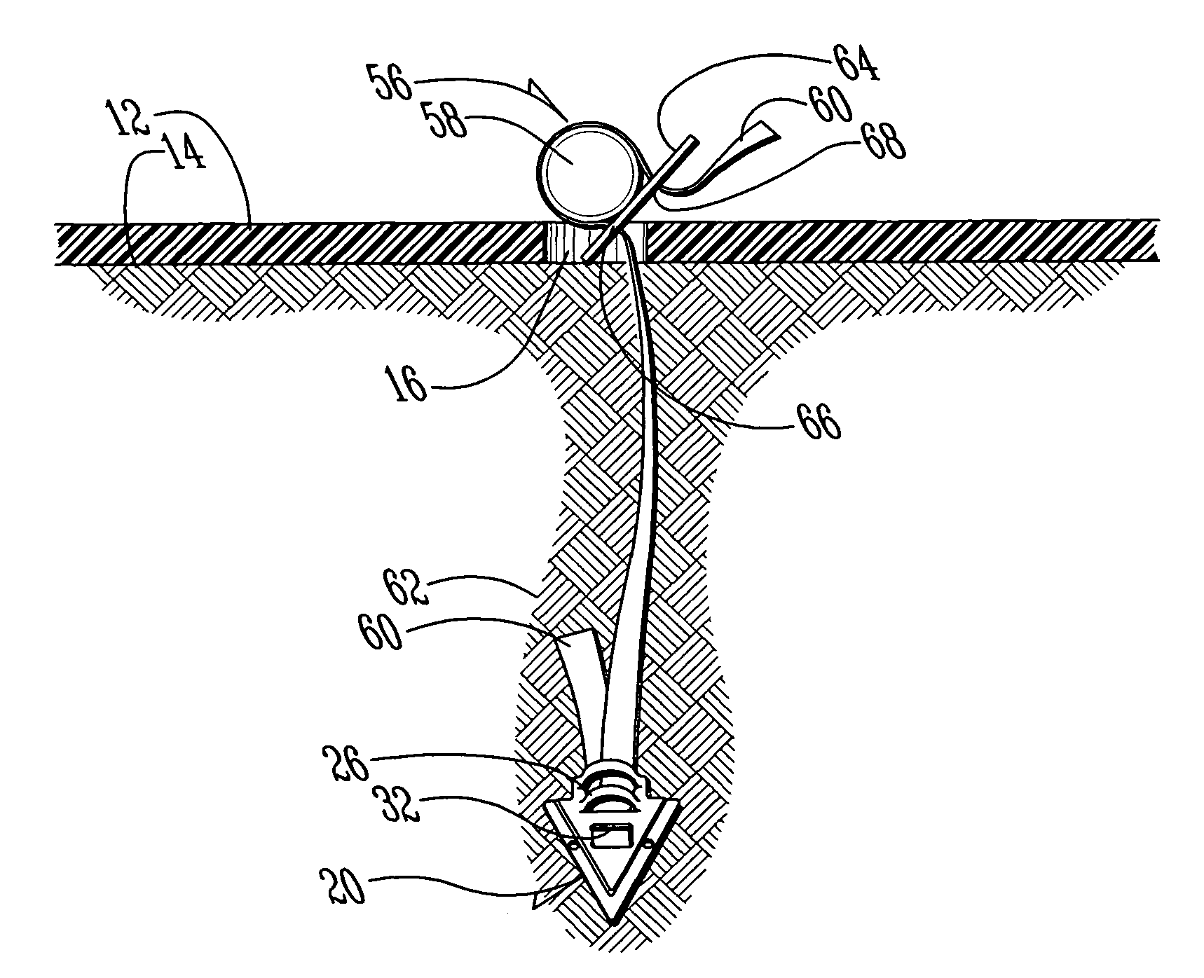
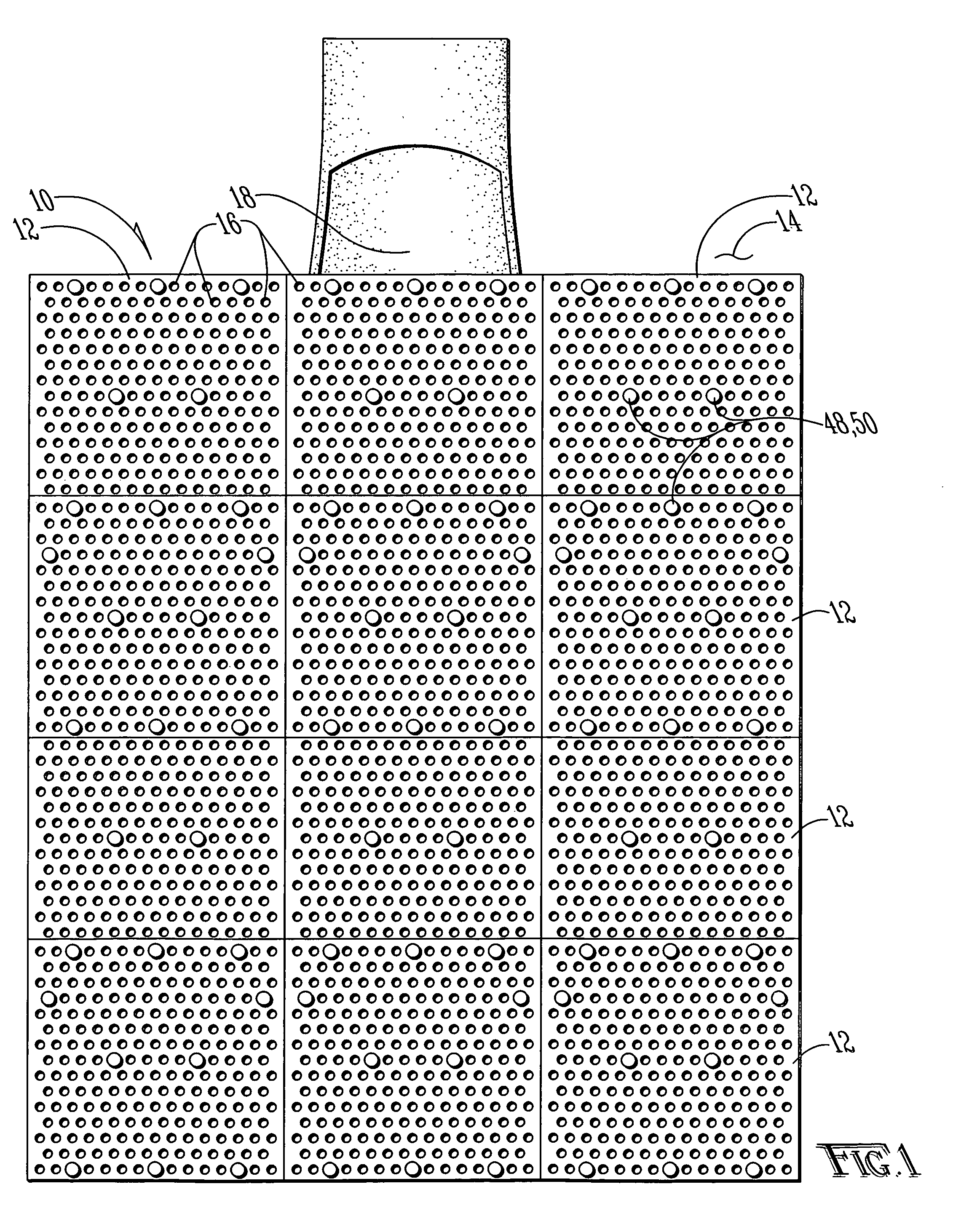
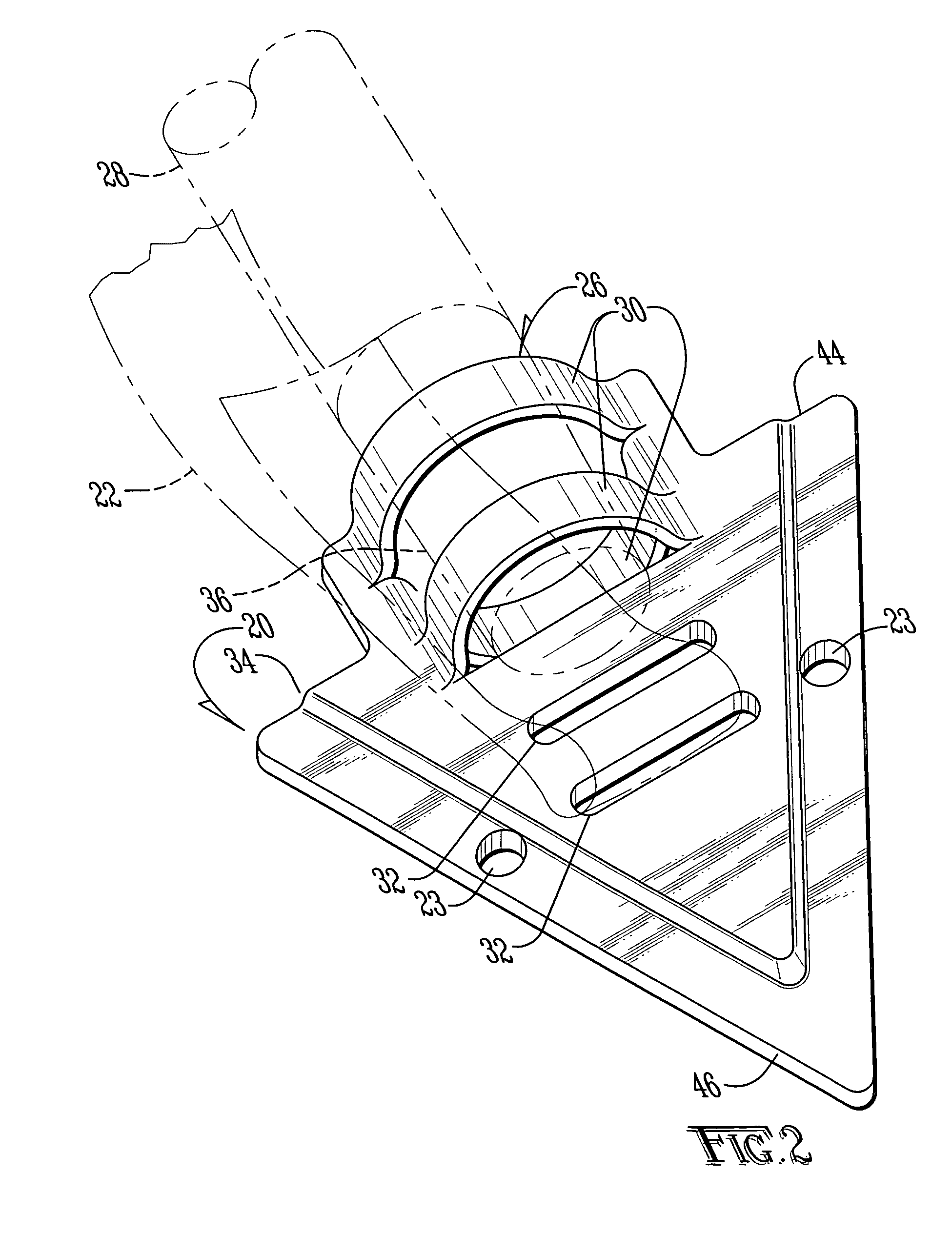
[0026]An erosion control mat anchor system according to this invention is shown generally as (10) in FIG. 1. A plurality of the systems (10) are shown securing a plurality of erosion control transition mats (12), such as those described in U.S. Letters Pat. No. 6,951,438, which is incorporated herein by this reference. The system (10) may, of course, be used in association with any type of erosion control surface, such as plastic sheeting, canvas, sod, a turf reinforcement mat, or any other erosion control surface. As shown, the anchor system (10) of the present invention is used to secure the erosion control mats (12) in an overlapped relationship. The anchor systems (10) provided at the upstream and downstream portions of the erosion control transition mats (12) extend through two erosion control transitions mats (12) tying them together, as well as securing them over the erosion susceptible surface (14), such as dirt, sod or secondary erosion control surface such as a turf reinfo...


PUM


Abstract

An anchor system for an erosion control surface. The system includes a resilient strap and a one-way retainer, which may be inserted utilizing a single operator and inexpensive tools. The resiliency of the system biases the erosion control surface into the ground and prevents undesired movement of the erosion control surface.

Description

BACKGROUND OF THE INVENTION[0001]1. Field of the Invention[0002]The present invention relates in general to an anchor system for anchoring material to the ground and, more particularly, to a system for anchoring an erosion control surface to the ground.[0003]2. Description of the Prior Art[0004]The Clean Water Act and subsequent legislation requires storm water to be discharged in a non-erosive manner. Unfortunately, storm water pipe outlets and the like used to divert water runoff are highly erosive at their outlets as the result of velocity and shear force problems associated with the funneling of water toward a narrow outlet. Erosion control associated with such outlets involves economic, physical and logistical problems. Traditionally, storm water is transported from a street or parking lot in a storm water pipe to a conveyance, such as a stream or river. Storm water may also be drained from a permanent structure, like a parking lot, at designated outlets where it flows overland...

Claims


Application Information

Patent Timeline
Patent Type & Authority Patents(United States)
IPC IPC(8): E02D17/20E02D5/80
CPCE02D5/74E02D5/803E02D17/202E03F5/0401E03F5/041
Inventor CARPENTER, THOMAS J.
Owner LANDMARK EARTH SOLUTIONS
Learn More