Nanoporous articles and methods of making same

a technology of nanoporous articles and methods, applied in the field of nanoporous articles, can solve the problems of individual blocks in the stack shifting positionally, affecting downstream pumps, compressors, valves and fluid-utilizing process equipment, generating carbon dust or fines, etc., and achieve the effect of enhancing character

Active Publication Date: 2011-01-04
ENTEGRIS INC
View PDF75 Cites 20 Cited by
  • Summary
  • Abstract
  • Description
  • Claims
  • Application Information

AI Technical Summary

Benefits of technology

[0015]Still another aspect of the invention relates to a nanoporous carbon composite including nanoporous carbon having porosity that is at least partially filled with material imparting to the composite an enhanced character with respect to characteristics selected from the group consisting of hardness, wear-resistance and toughness, as compared with the nanoporous carbon alone.

Problems solved by technology

The stack of disc- or puck-form blocks of the carbon adsorbent material is efficient as a sorptive matrix for a variety of fluids, e.g., fluids used for semiconductor device manufacturing, but suffers the disadvantage that individual blocks in the stack can shift positionally, and impact or rub against the interior wall surfaces of the containment vessel and / or against one another, in response to movement of the vessel or shocks or impacts thereon, e.g., during transport of the vessel from a manufacturing facility to a fluid filling or end use facility.
In addition to causing unwanted noise, such impact and / or rubbing of the monolithic blocks can damage the blocks as well as cause them to generate carbon dust or fines.
Such dust or fines are carried in the dispensed fluid stream, and adversely affect downstream pumps, compressors, valves and fluid-utilizing process equipment.
Another problem associated with the use of low-pressure adsorbent-based fluid storage and dispensing vessels that dispense fluid to vacuum or low pressure environments is that it becomes disproportionately more difficult to desorb and dispense the fluid as the inventory of fluid in the vessel drops to residual levels.
The pressure drop from the vessel to a downstream tool or flow circuitry may in fact become too low to support dispensing, with the result that a substantial amount of fluid remains as so-called “heels” on the adsorbent in the vessel when dispensing can no longer take place.
This circumstance results in reduced gas utilization efficiency.
This approach, however, is not practical in many fluid dispensing applications, since the associated process facility is not adaptable to such external heating.
In addition to the issues described above related to fluid storage and dispensing systems, carbon is conventionally used as a component in high-strength composites, as a reinforcing medium.
In addition, carbon is used in composite materials applications as a continuous medium in vitreous carbon composites, which are useful in a variety of tribological applications, but suffer the inherent disadvantage of being highly brittle and therefore subject to cracking and loss of physical integrity.

Method used


Image

  • Nanoporous articles and methods of making same
  • Nanoporous articles and methods of making same
  • Nanoporous articles and methods of making same

Examples


example 1

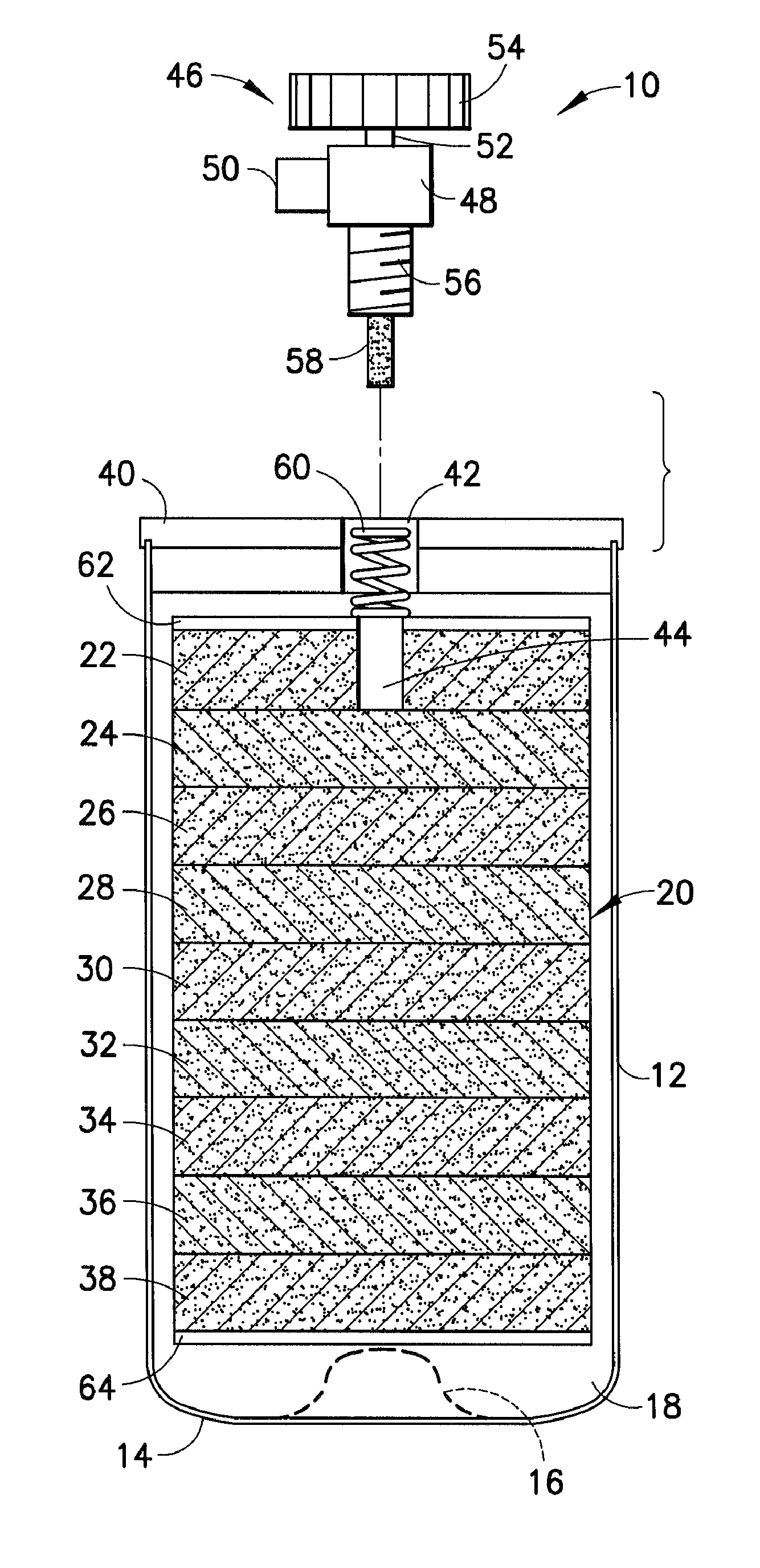
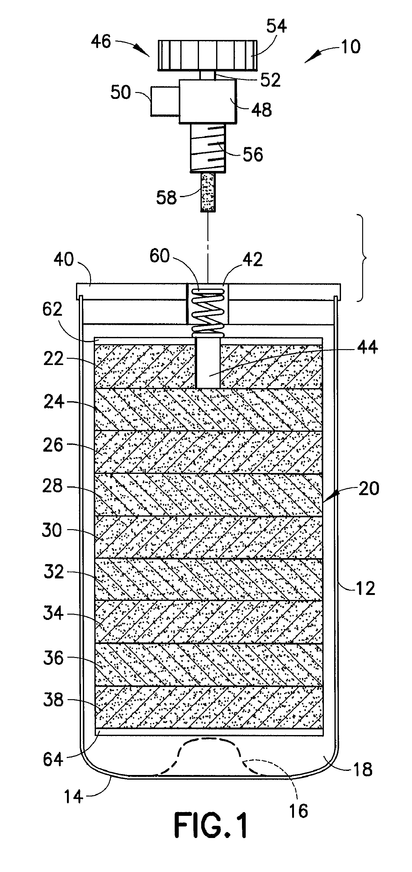
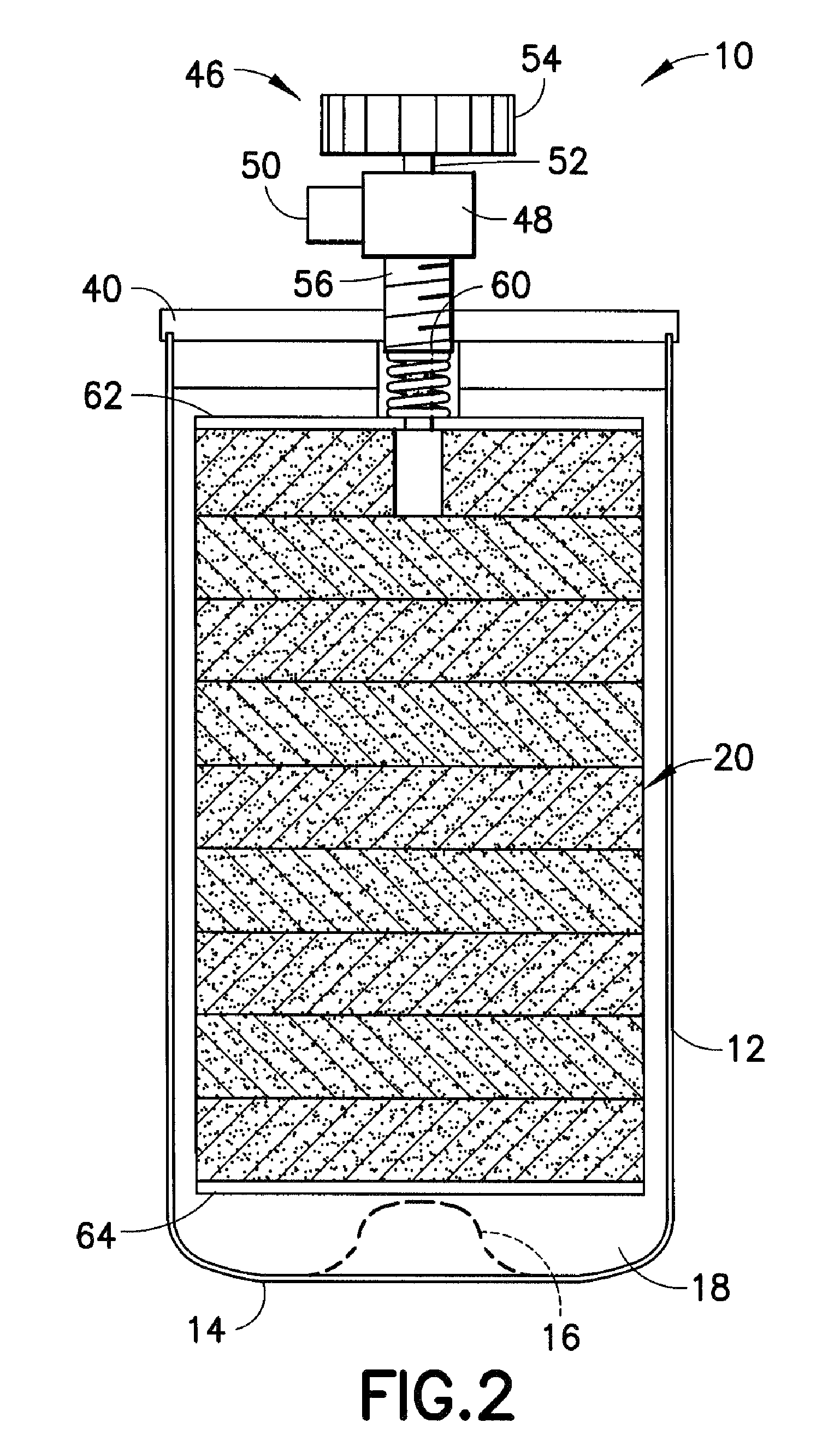
[0200]In a standard fill procedure for boron trifluoride gas storage and dispensing packages, a cylindrical gas vessel is filled with a stack of activated carbon pucks, and a headpiece is welded to the gas cylinder. The cylinder fabrication then is completed by installation of a valve head assembly on the headpiece.

[0201]The resulting gas supply package with the valve in the valve assembly in an open position, is charged with helium gas at 300 psi pressure through the valve head assembly, and the valve then is closed. The helium-containing package next is placed in a vacuum chamber. The vacuum chamber is subjected to high vacuum, with a helium gas detector monitoring any leakage of the helium that may occur from the vessel.

[0202]If the vessel by such testing is determined to be leak-tight in character, then the helium is removed from the vessel by applying a high vacuum to the system, followed by a bake-out at elevated temperature. This procedure drives off residual volatile compone...

example 2

[0203]A gas supply package is fabricated as in Example 1, but prior to contacting with helium gas, the carbon adsorbent is exposed to water vapor so that water vapor is taken up by the adsorbent. The amount of water vapor taken up by the adsorbent can be in a range of from 5% to 40% by weight, or more, based on the weight of carbon adsorbent.

[0204]The gas supply package then is pressurized with helium at 300 psi, as described in Example 1. The vessel after removal of helium is then subjected to bake-out of the adsorbent, cooling of the vessel to ambient temperature and is then charged with boron trifluoride gas.

[0205]Results of Comparative Testing

[0206]A comparative test was carried out to determine the efficacy of the pretreatment method of Example 2 over the standard method of Example 1.

[0207]Two series of comparative tests were conducted.

[0208]In the first series, each of four gas cylinder vessels was loaded with 2550 grams of carbon adsorbent, in the form of a stack of puck arti...


PUM

PropertyMeasurementUnit
temperatureaaaaaaaaaa
pressureaaaaaaaaaa
temperatureaaaaaaaaaa

Abstract

An adsorbent having porosity expanded by contact with a first agent effecting such expansion and a pressurized second agent effecting transport of the first agent into the porosity, wherein the adsorbent subsequent to removal of the first and second agents retains expanded porosity. The adsorbent can be made by an associated method in which materials such as water, ethers, alcohols, organic solvent media, or inorganic solvent media can be utilized as the first agent for swelling of the porosity, and helium, argon, krypton, xenon, neon, or other inert gases can be employed as the pressurized second agent for transport of both agents into the porosity of the adsorbent, subsequent to which the agents can be removed to yield an adsorbent of increased capacity for sorbable fluids, e.g., organometallic compounds, hydrides, halides and acid gases. Also described is a nanoporous carbon composite having porosity that is at least partially filled with material imparting to the composite an enhanced character with respect to characteristics selected from the group consisting of hardness, wear-resistance and toughness, as compared with the nanoporous carbon alone.

Description

CROSS-REFERENCE TO RELATED APPLICATIONS[0001]This application is a continuation-in-part under 35 USC 120 of international patent application PCT / U.S.07 / 61255 filed Jan. 29, 2007 and international patent application PCT / U.S.07 / 61255 filed Jan. 29, 2007, each in turn claiming the benefit of priority under 35 USC 119 of U.S. provisional patent application 60 / 763,258 filed Jan. 30, 2006, the benefit of priority of which is also hereby claimed. The disclosures of such international patent applications and the disclosure of U.S. provisional patent application 60 / 763,258 are hereby incorporated herein by reference, in their respective entireties, for all purposes.FIELD OF THE INVENTION[0002]The present invention relates to nanoporous articles, e.g., carbonaceous materials having utility for fluid storage / dispensing and desulfurization and other applications, and to apparatus and methods utilizing same. The present invention also relates to nanoporous carbon materials having utility for flu...

Claims


Application Information

Patent Timeline
Patent Type & Authority Patents(United States)
IPC IPC(8): B01D53/02B01J20/20C01B32/336
CPCB01D53/0415F17C11/007B01J20/20B01J20/28011B01J20/28014B01J20/28023B01J20/28033B01J20/28042B01J20/28052B01J20/2808B01J20/28097B82Y30/00C01B3/0021C01B13/0251C10G25/003C10G45/02C10G67/06F17C11/00B01D2253/102B01D2253/1122B01D2253/202B01D2253/308B01D2253/311B01D2253/342B01D2256/24B01D2257/30B01D2258/0216B01D2259/40096B01D2259/4146B01D2259/4525B01D2259/455B01J2220/66Y02E60/321Y02E60/325Y10S95/903C10G2300/1033C10G2300/1044C10G2300/1051C10G2300/1055C10G2300/202C10G2300/207B01D53/0446Y02E60/32Y10T428/249956Y10T428/249957
Inventor CARRUTHERS, J. DONALDDIMEO, JR., FRANKBOBITA, BRIAN
Owner ENTEGRIS INC
Why Eureka
Try Eureka