Spindle motor having a fluid dynamic bearing system

a technology of bearing system and spindle motor, which is applied in the direction of sliding contact bearings, mechanical equipment, dynamo-electric components, etc., can solve the problems of inability to harden the cones to increase the resistance to wear, and achieve the effect of simple design, easy measurement and monitoring, and precise and reliable assembly of the rotor

Active Publication Date: 2011-01-11
MINEBEAMITSUMI INC
View PDF7 Cites 3 Cited by
  • Summary
  • Abstract
  • Description
  • Claims
  • Application Information

AI Technical Summary

Benefits of technology

[0007]The motor design according to the invention, whose core elements are two simple bearing plates that are enclosed by separate fluid dynamic bearing systems, provides reliable, low-cost manufacture thanks to the simple shapes of the components used and its less complex assembly, and it has high structural stiffness thanks to the shaft being fixed at both ends.
[0012]Various sealing concepts can be used to prevent bearing fluid from leaking out of the bearing gap and to provide sufficient bearing fluid for the functional capability of the motor during its entire useful life. One possibility is to provide a tapered reservoir narrowing towards the motor interior between the stopper plates and the hub, called a taper seal, where an appropriate slant may be given either solely to the outside diameter of the stopper plates, or to the inside diameter of the hub or perhaps to both sides. Furthermore, the two bearing systems can each be sealed towards the motor interior by a narrow gap formed between the bushing and the hub, the gap being provided with appropriate pumping patterns. The well-known sealing concept of an active pumping seal finds application here accordingly.
[0015]The simple design of the components ensures precise and reliable assembly of the rotor, since, using a relatively uncomplicated process, the hub can be machined in such a way that after the bearing plates have been mounted, the axial runout of the entire rotor is minimized and any external mechanical forces acting on the rotor are transferred positively to the stopper plates. The axial play and position of the rotor is determined by the installation of the stopper plates, which, due to the large, level contact surfaces, can be easily measured and monitored in the assembly process.

Problems solved by technology

Furthermore, hardening the cones to increase their resistance to wearing is usually impossible.

Method used


Image

  • Spindle motor having a fluid dynamic bearing system
  • Spindle motor having a fluid dynamic bearing system
  • Spindle motor having a fluid dynamic bearing system

Examples


first embodiment

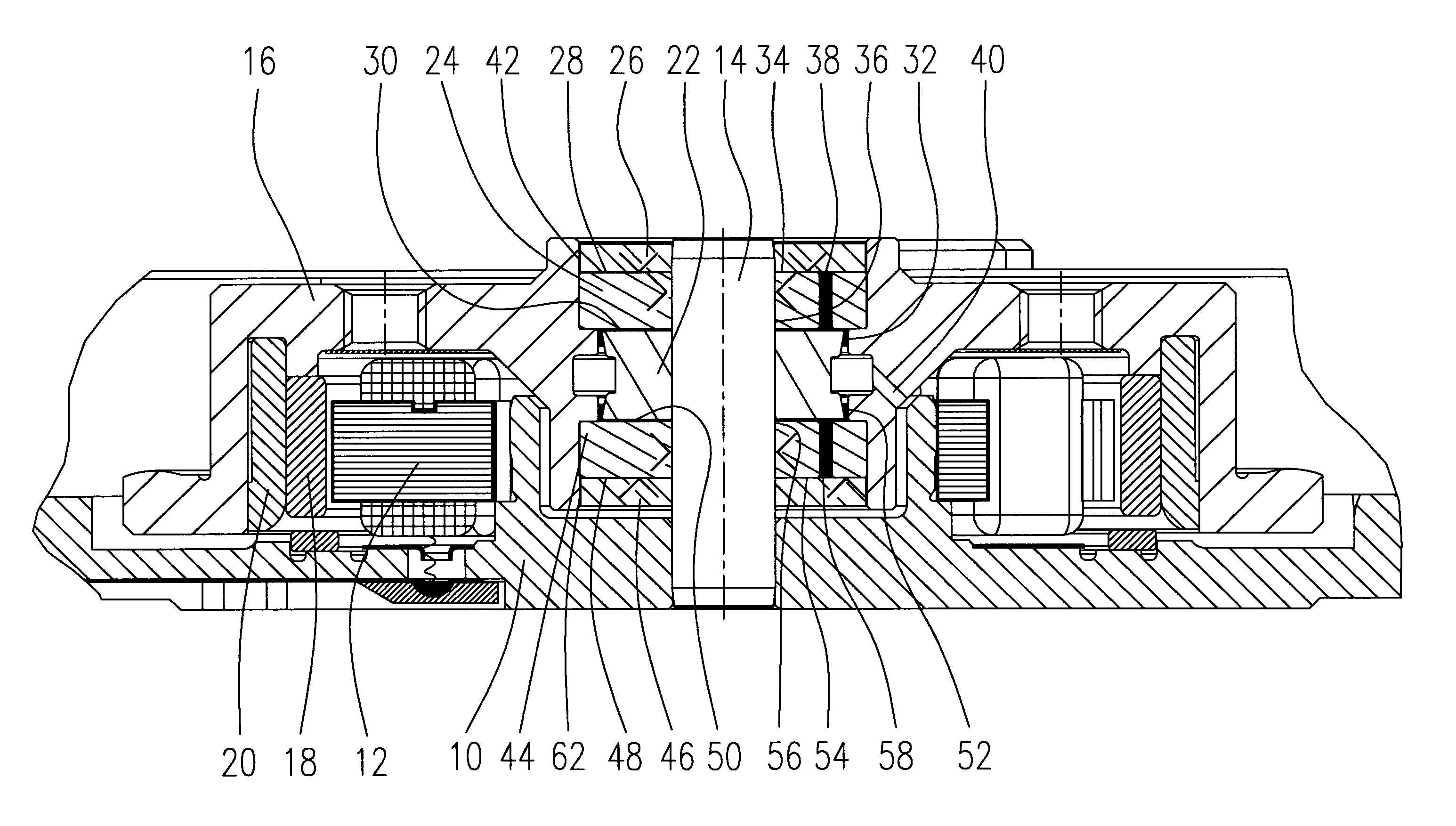
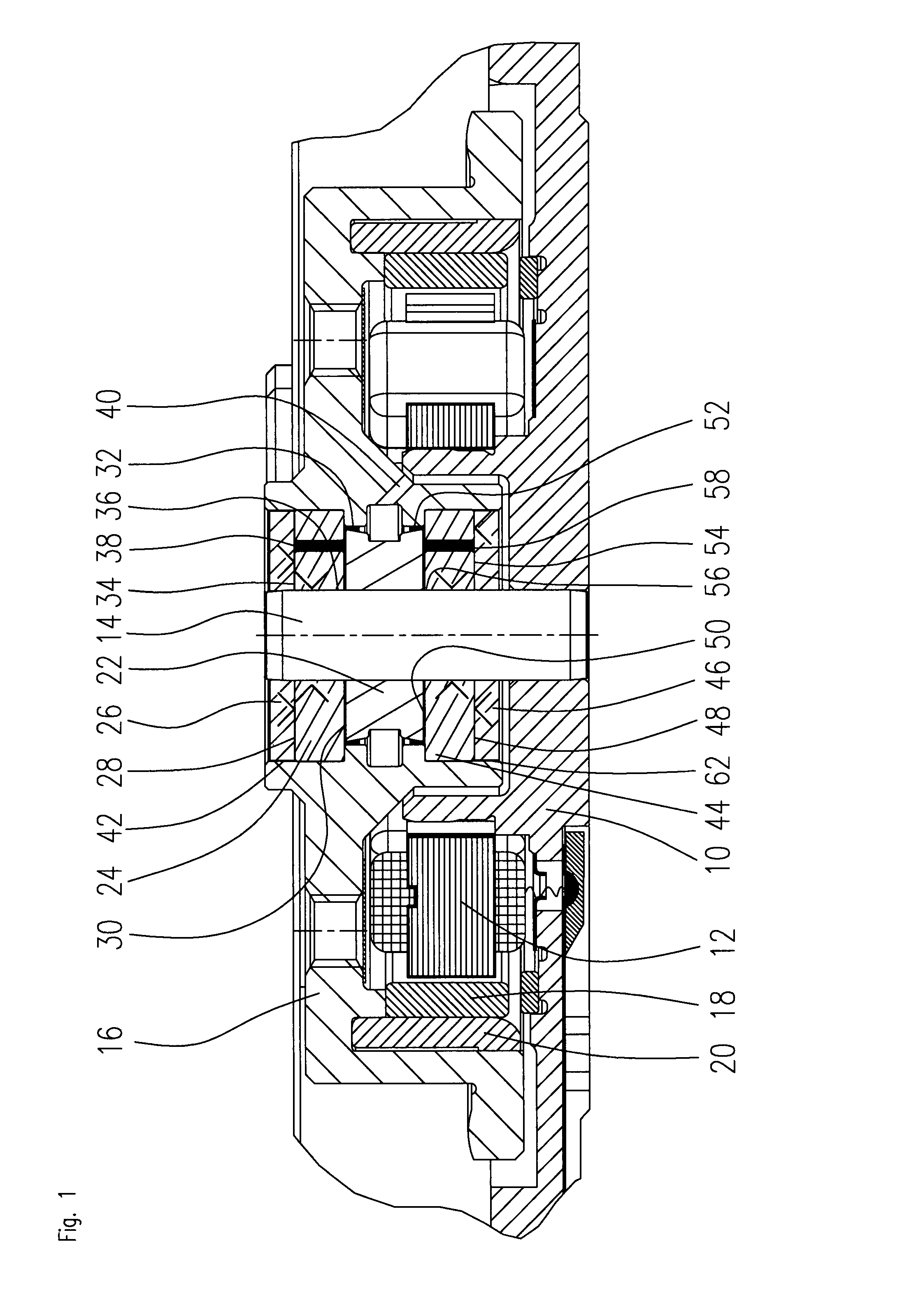
[0019]FIG. 1 shows a section through a spindle motor according to the invention having a fluid dynamic seal.

[0020]The spindle motor comprises a stationary base 10 on which a stator arrangement 12 is disposed in a conventional manner. A shaft 14 is fixedly accommodated in the base 10, the shaft being enclosed by a hub 16 that is rotatably supported with respect to the shaft 14. At its circumference, the hub 16 comprises a magnet arrangement 18 having an appropriate magnet yoke 20 that encloses the stator arrangement 12 and together with the stator arrangement forms an electromagnetic drive system.

[0021]The hub 16 is rotatably supported with respect to the shaft 14 by means of two independent fluid dynamic bearing systems that are disposed between the hub 16 and the shaft 14. A bushing 22 is disposed on the shaft 14 that separates the two fluid dynamic bearing systems from one another.

[0022]A first fluid dynamic bearing system is formed by a first bearing plate 24 that is disposed at ...

second embodiment

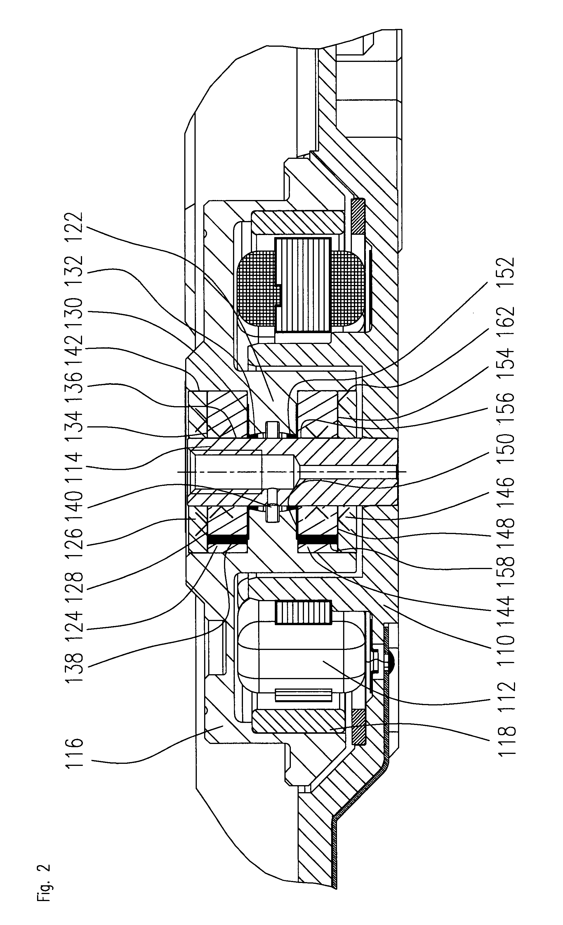
[0026]FIG. 2 shows a section through a spindle motor according to the invention having a fluid dynamic seal.

[0027]The spindle motor comprises a stationary base 110 on which a stator arrangement 112 is disposed in a conventional manner. A shaft 114 is fixedly accommodated in the base 110, the shaft being enclosed by a hub 116 that is rotatably supported with respect to the shaft 114. The hub 116 comprises a magnet arrangement 118 that encloses the stator arrangement 112 and together with the stator arrangement forms an electromagnetic drive system.

[0028]The hub 116 is rotatably supported with respect to the shaft 114 by means of two independent fluid dynamic bearing systems that are disposed between the hub 116 and the shaft 114. A collar 122 taking the form of a bushing is formed at an inner circumferential surface of the hub, the collar enclosing the shaft at a slight spacing and separating the two fluid dynamic bearing systems from one another. The collar 122 can, for example, be ...

third embodiment

[0033]FIG. 3 shows a section through a spindle motor according to the invention having a fluid dynamic seal.

[0034]The spindle motor comprises a stationary base 210 on which a stator arrangement 212 is disposed in a conventional manner. A shaft 214 is fixedly accommodated in the base 210, the shaft being enclosed by a hub 216 that is rotatably supported with respect to the shaft 214. The hub 216 comprises a magnet arrangement 218 having an appropriate magnet yoke 220 that encloses the stator arrangement 212 and together with the stator arrangement forms an electromagnetic drive system.

[0035]The hub 216 is rotatably supported with respect to the shaft 214 by means of two independent fluid dynamic bearing systems that are disposed between the hub 216 and the shaft 214. A bushing 222 is disposed on the shaft 214 that separates the two fluid dynamic bearing systems from one another.

[0036]A first fluid dynamic bearing system is formed by a first bearing plate 224 that is disposed at the i...


PUM


Abstract

The invention relates to a spindle motor having a fluid dynamic bearing system that comprises a base (10), a stationary shaft (14) connected to the base, a hub (16) rotatably supported with respect to the shaft and two bearing plates (24, 44) that are disposed at a mutual spacing about the shaft and connected to the hub. A bushing (22) is provided that is disposed between the bearing plates and separated from them by a gap (30, 50) at least partly filled with a bearing fluid. There are two stopper plates (26, 46) that are fixedly connected to the shaft, each abutting one side of each bearing plate and separated from the bearing plate by a bearing gap (28, 48) filled with bearing fluid. This results in two independent fluid dynamic bearing systems, each of which is disposed about a bearing plate. The motor is driven by an electromagnetic drive system.

Description

BACKGROUND OF THE INVENTION[0001]The invention relates to a spindle motor having a fluid dynamic bearing system, used in particular for hard disk drives.PRIOR ART[0002]Spindle motors having fluid dynamic bearing systems can be divided into two different groups: motors having a rotating shaft and a bearing system that is usually open at only one end (e.g. a single plate design) and motors having a stationary shaft. A distinct advantage afforded by the second group is the possibility of connecting the stationary shaft of the spindle motor to the housing not only at one end alone but also of fixing it at the other end to the top cover of the housing. Hence, these types of motors acquire considerably greater structural stiffness, making them particularly suitable for hard disk drives having special requirements, such as a large number of storage disks and a high number of revolutions for servers or for notebooks that are subject to more frequent or stronger vibrations during normal oper...

Claims


Application Information

Patent Timeline
Patent Type & Authority Patents(United States)
IPC IPC(8): F16C32/06
CPCF16C17/10H02K5/1677F16C33/107F16C2370/12F16C17/107
Inventor DRAUTZ, FRANK
Owner MINEBEAMITSUMI INC
Why Eureka
Try Eureka