Motor driving apparatus

a technology for driving apparatuses and motors, applied in the direction of motor/generator/converter stoppers, dynamo-electric gear control, motor/generator/converter stoppers, etc., can solve the problems of difficult to reduce the amount of current from the power source to a desirable level, the supply current from the power source is interrupted, and the capacitor capacitance is reduced, so as to control and optimize the amount of electric energy supplied.

Active Publication Date: 2011-01-11
FANUC LTD
View PDF26 Cites 15 Cited by
  • Summary
  • Abstract
  • Description
  • Claims
  • Application Information

AI Technical Summary

Benefits of technology

[0014]An object of the present invention is to provide a motor driving apparatus for controlling the amount of electric energy supplied from a capacitor so as to limit the current input from a power source to any desired value and for efficiently using electric energy stored in the capacitor so as to reduce the capacitance of the capacitor.
[0025]The motor driving apparatus may have a low-pass filter for reducing an effect of high frequency components superimposed on the command value. The low-pass filter may take the maximum value within a prescribed period of the command value as a command value.
[0027]The present invention can control and optimize the amount of electric energy supplied from the capacitor and reduce the capacitance of the capacitor because of the above structure.
[0028]In addition, the present invention can control the amount of power source current flowing into the motor driving apparatus to a desired value, so the amount of power source current flowing into the motor driving apparatus can be set according to the limit of the power source current of a power source facility for which the motor driving apparatus is to be installed.

Problems solved by technology

In the above motor driving apparatus, during power running of the motor, electric energy stored in the capacitor is not controlled or control is made so as to prevent a prescribed current amount from being exceeded after the switch of the discharge circuit is turned on, so electric energy stored in the capacitor is discharged rapidly, making it difficult to supply electric energy from the capacitor to the inverter for a sufficient period of time.
In addition, supply current from the power source is interrupted or reduced according to the amount of electric energy supplied from the capacitor to the inverter, so it is difficult to reduce the amount of current from the power source to a desirable level.

Method used


Image

  • Motor driving apparatus
  • Motor driving apparatus
  • Motor driving apparatus

Examples


first embodiment

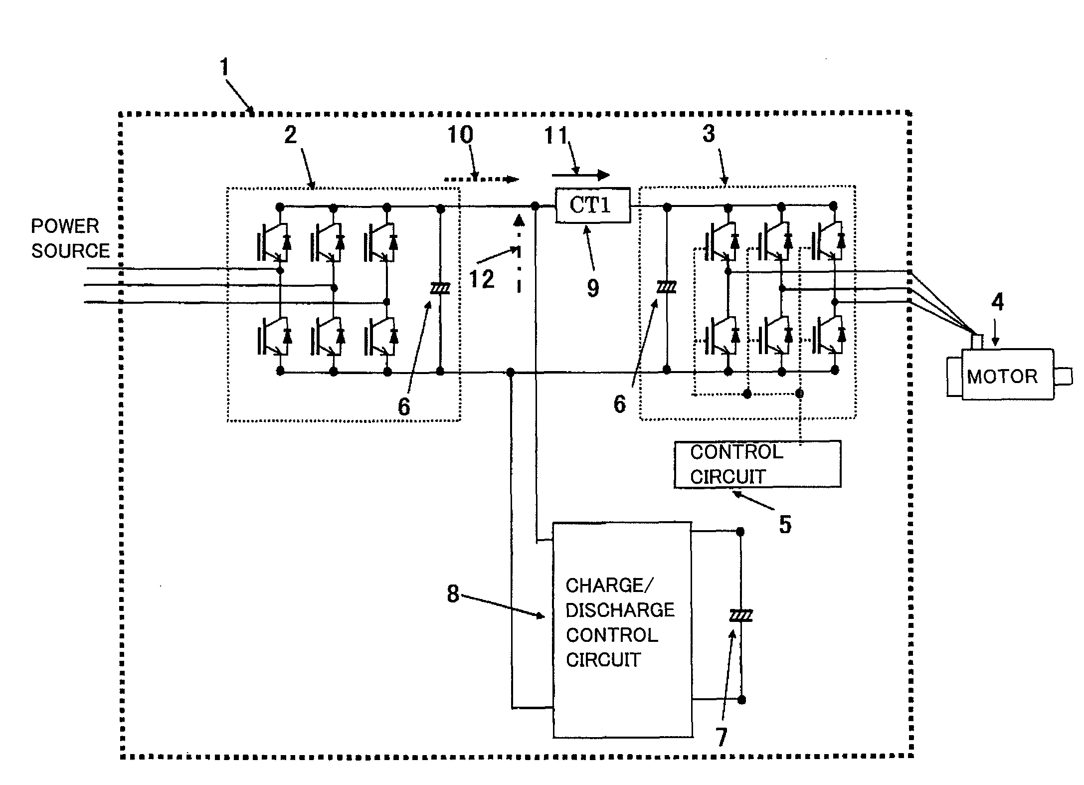
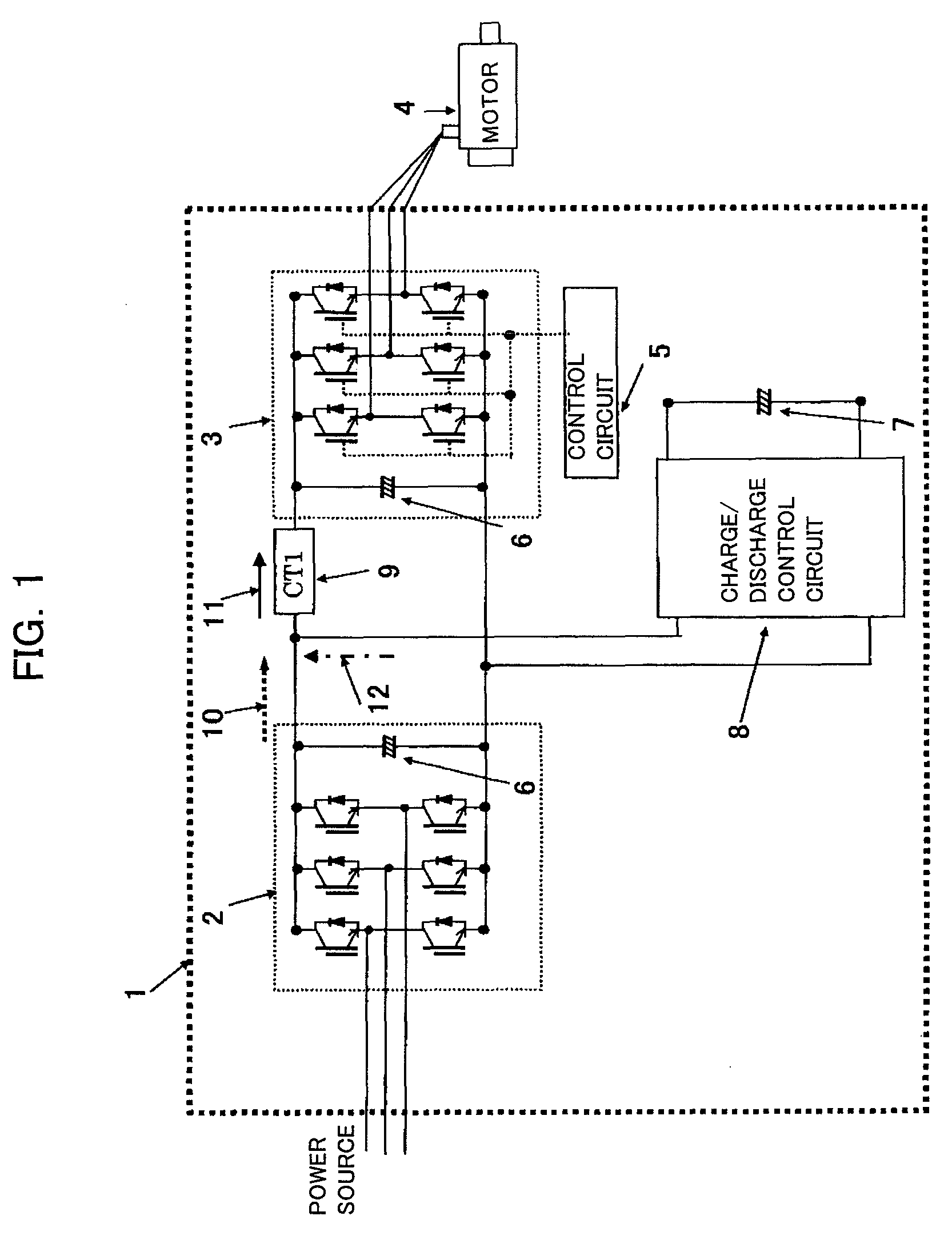
[0044]FIG. 1 is a schematic structural diagram showing a motor driving apparatus according to the present invention.

[0045]A voltage is supplied to a motor driving apparatus 1 in this embodiment by a three-phase AC power source. A converter 2 converts the supplied AC voltage into a DC voltage. An inverter 3 converts the converted DC voltage into an arbitrary AC voltage of an arbitrary frequency and supplies it to a motor 4. A smoothing capacitor 6 is a DC link that is connected between the converter 2 and the inverter 3, smoothes a DC voltage converted by the converter 2, and inputs the smoothed DC voltage to the inverter 3.

[0046]The converter 2 includes bridge circuits comprising power elements (for example, transistors) and anti-parallel diodes connected to the power elements. During power running, the converter 2 converts a three-phase AC power source into a DC voltage through full wave rectification using six diodes; during power regeneration, the converter 2 sends regenerative p...

second embodiment

[0084]Next, the motor driving apparatus according to the present invention will be described with reference to FIGS. 11 to 14.

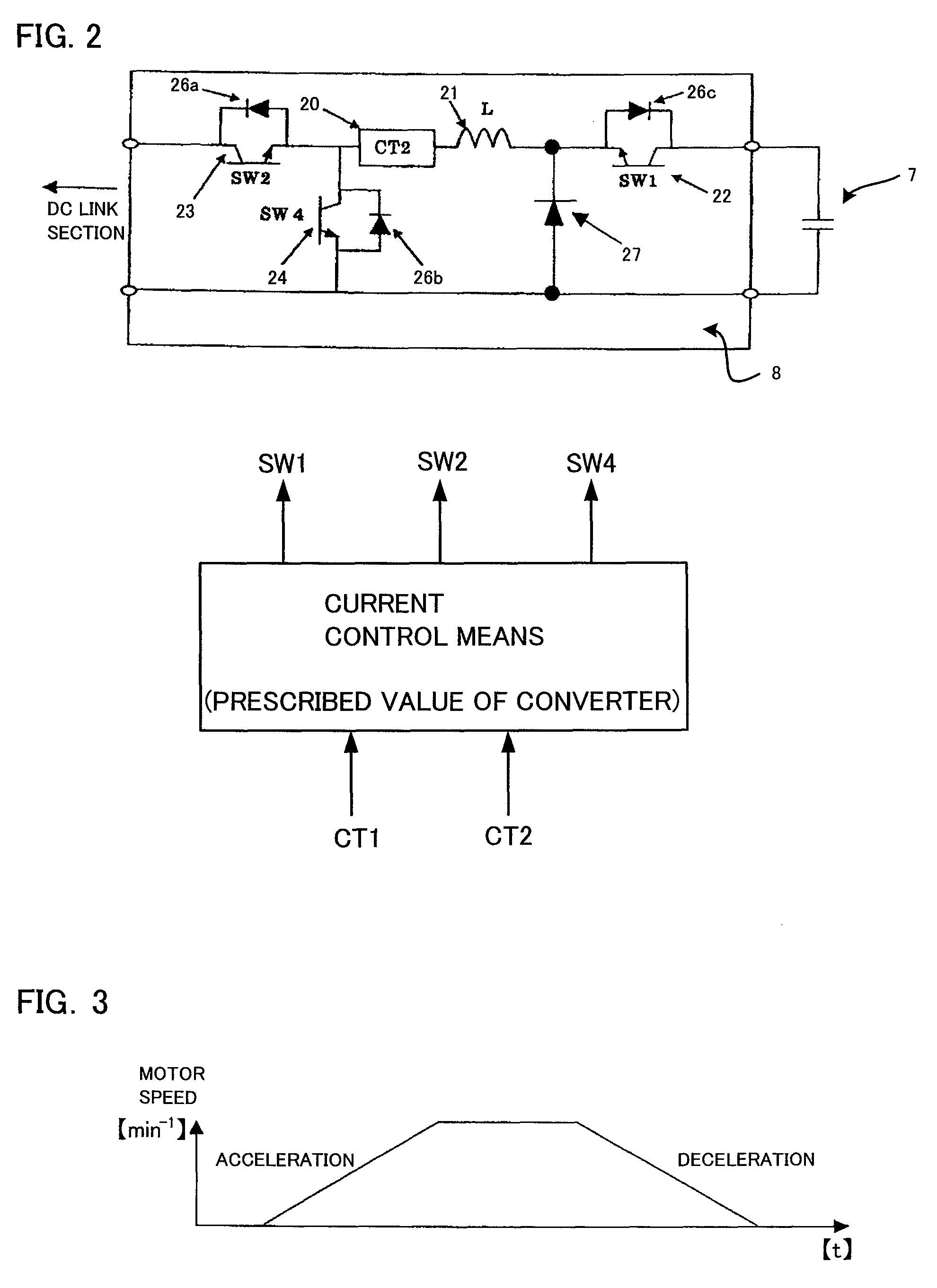
[0085]According to this embodiment, current control means in the motor driving apparatus stops discharge current from the charge / discharge control circuit when the amount of input current or input power of the converter or the amount of output current or output power of the converter is reduced to a prescribed value.

[0086]In FIG. 11, a third current sensor (CT3) detects converter output current 10.

[0087]FIG. 13 shows a hysteresis comparator that compares converter output current 10 detected by the current sensor 13 (CT3) with a prescribed current value; the hysteresis comparator turns on the discharge control switch 22 (SW1) of the charge / discharge control circuit 8 shown in FIG. 12 when converter output current 10 is equal to or more than a prescribed value.

[0088]The amount of inverter input current 11 shown in FIG. 11 depends on the output of the motor 4 an...


PUM


Abstract

A motor driving apparatus comprises a charge / discharge control circuit for controlling charge to or discharge from a capacitor connected in parallel in a link section between a converter and an inverter, and a current control means for controlling discharge current from the charge / discharge control circuit. The current control means controls discharge current from the charge / discharge control circuit based on input current to the inverter or output current from the converter so that output current from the converter is equal to a prescribed value.

Description

RELATED APPLICATIONS DATA[0001]This application claims priority under 35 U.S.C. §119 and / or §365 to Japanese Application No. 2008-048212 filed Feb. 28, 2008, the entire contents of which are incorporated herein by reference.BACKGROUND OF THE INVENTION[0002]1. Field of the Invention[0003]The present invention relates to a motor driving apparatus that supplies, during power running, electric energy stored in a capacitor so as to reduce current supplied from a power source.[0004]2. Description of the Related Art[0005]A motor driving apparatus comprising a converter for converting an AC voltage from an AC power source to a DC voltage, an inverter for converting the converted DC voltage back to an AC voltage, a capacitor connected in parallel with a DC link section between the converter and the inverter, and a charge / discharge control circuit for controlling charge to and discharge from the capacitor is disclosed in, for example, Japanese Patent Application Laid-Open No. 2000-141440.[000...

Claims


Application Information

Patent Timeline
Patent Type & Authority Patents(United States)
IPC IPC(8): H02P3/14H02P3/18H02P21/36H02P23/07H02P27/06
CPCH02J7/345H02M5/4585
Inventor IWASHITA, YASUSUKEYAESHIMA, MAMORUYAMADA, YUUICHISHIROUZU, MASATOMOSAKAI, KOUJIROU
Owner FANUC LTD
Why Eureka
Try Eureka