
Frequency-locking device and frequency-locking method thereof

a frequency-locking device and frequency-locking technology, which is applied in the direction of synchronisation signal speed/phase control, instruments, transmission monitoring, etc., can solve the problems of increasing the memory cost the circuit design of the frequency-locking device b>10/b> becomes more complicated and defective, and the production cost of the circuit design is reduced. , the effect of less complicated circuit design

Inactive Publication Date: 2011-01-11
SONIX TECH
View PDF7 Cites 0 Cited by
  • Summary
  • Abstract
  • Description
  • Claims
  • Application Information

AI Technical Summary

Benefits of technology

The present invention provides an automatically frequency-locking device for a USB device that is less complicated and cheaper than prior art. The device includes a digitally-controlled oscillator, a packet analyzing unit, a control unit, and a voltage adjusting unit. The device uses a reference signal generated from analyzing a universal serial bus signal to adjust the frequency of the output frequency signal. The control unit generates a calibration signal and determines the number of erroneous transmission times to adjust the frequency. The voltage adjusting unit applies a voltage level to the transmission line based on the control signal. The invention has advantages of simplified circuit design and lower production cost but also has increased times for adjusting frequency via the soft plug / unplug method. The invention solves the problem of limited frequency adjustment in general USB devices and ensures that the output frequency signal is locked to a specific or predetermined frequency.

Problems solved by technology

However, the way of generating the correction signal FACTOR according to the all fields shown in FIG. 1B of the input signal PACKET of the universal serial bus makes the actual design and operation of circuit more complicated and defective.
Since one-time reference to all of the digits of the token packet is required, the circuit design of the frequency-locking device 10 becomes more complicated.
Besides, the great amount of memory space occupied by the look-up table inside the frequency-locking device 10 increases the memory cost for the frequency-locking device 10.

Method used


Image

  • Frequency-locking device and frequency-locking method thereof
  • Frequency-locking device and frequency-locking method thereof
  • Frequency-locking device and frequency-locking method thereof

Examples


Embodiment Construction

[0023]Reference will now be made to the drawings in which the various elements of the present invention will be given numerical designations and in which the invention will be discussed so as to enable one skilled in the art to make and use the invention.

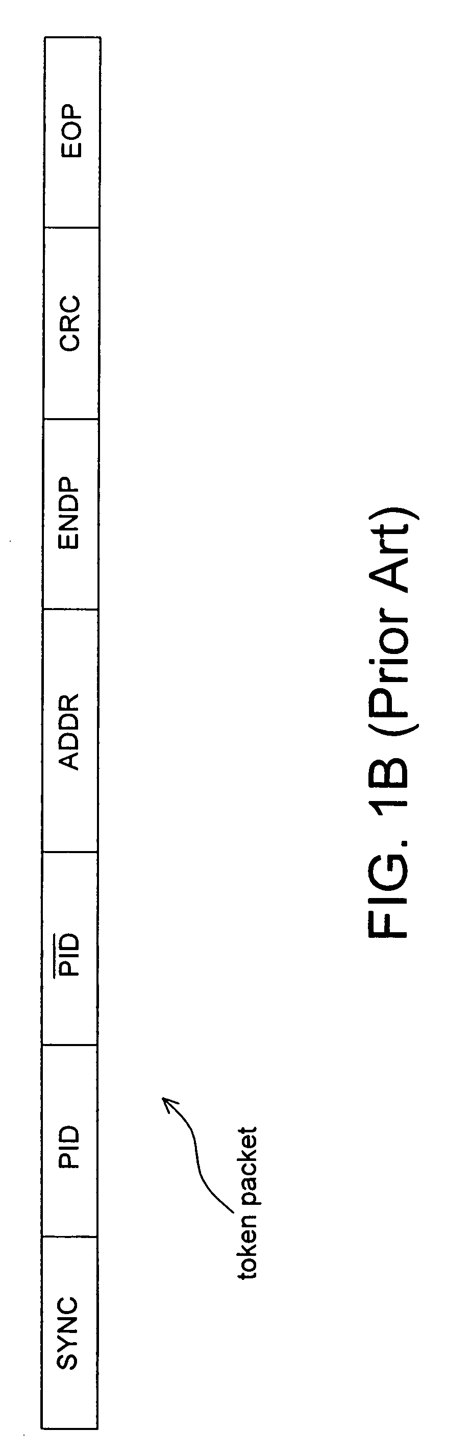
[0024]The transmission of a universal serial bus (USB) is performed via three packets including token packet, data packet, and handshake packet. A transaction starts when a host controller or a hub controller sends out a token packet such as shown in FIG. 1B. The token packet recites the transaction type, transaction direction, device address, and endpoint number. In transaction, data is transmitted from the host controller to the universal serial bus device or from the universal serial bus device to the host controller, and the transmission direction is identified by the token packet. Meanwhile, the submitting side of the transaction sends out a data packet and the other side sends out a handshake packet for response to indicate wh...


PUM


Abstract

The invention proposes a simple method suitable for automatically locking frequency during USB data communication. Based on the soft plug / unplug concept proposed in the contents and the error handling mechanism defined in the USB specification, we can calibrate the clock frequency of the digitally controlled oscillator (DCO), through the token packets, to be within the acceptable frequency when USB device is attached to the host controller.

Description

BACKGROUND OF THE INVENTION[0001]1. Field of the Invention[0002]The present invention relates to a frequency-locking device and, more particularly, to a frequency-locking device applied to universal serial bus (USB).[0003]2. Description of the Related Art[0004]As shown in FIG. 1A, the frequency-locking device 10 applied to universal serial bus data communication was disclosed in U.S. Pat. No. 6,297,705 and U.S. Pat. No. 6,407,641. With regard to the frequency-locking device 10, the output clock of an oscillator 142 is locked to the rate of an incoming data stream input. The object of this technology is to precisely lock the output clock of the oscillator 142 to the rate of the incoming data stream without utilizing any external elements and provide multiple tuning phases during a single data packet input via coarse and / or fine tuning.[0005]Referring to FIG. 1A, the frequency-locking device 10 includes a control circuit 102 and an oscillator logic circuit 104. The control circuit 102...

Claims


Application Information

Patent Timeline
Patent Type & Authority Patents(United States)
IPC IPC(8): H04B17/00
CPCH03L7/06H04L7/10
Inventor LIN, YONG JHENGHUANG, WEN HSIANGCHEN, MIN-YI
Owner SONIX TECH
Learn More