Fault tolerant multi-node computing system using periodically fetched configuration status data to detect an abnormal node

a computing system and configuration status technology, applied in the field of multi-node computing system, can solve the problems of abnormal end, premature program end, and prohibitively high development cost of version diversity technique, and achieve the effect of less costly to develop application programs and less costly to execute application programs

Inactive Publication Date: 2011-01-11
NEC CORP
View PDF37 Cites 38 Cited by
  • Summary
  • Abstract
  • Description
  • Claims
  • Application Information

AI Technical Summary

Benefits of technology

[0013]Another object of the present invention is to prevent a multi-node parallel-running computing system from being adversely affected by a prolonged operation of an abnormal node.
[0014]A further object of the present invention is to provide a fault-tolerant multi-node parallel-running computing system which is less costly to develop application programs and less costly to execute an application program.

Problems solved by technology

However, the presence of a software fault results in a premature ending of the program known as abnormal end.
However, the development cost of this version diversity technique is prohibitively high.
However, one shortcoming of the prior art fault tolerance techniques is that, since the failure detection is performed only after results are obtained from all processing nodes, an abnormal node cannot quickly be detected before all processing results are obtained.
If the ping-pong system is used, a node failure may be detected instantly when there is no “pong” response at all.
However, it is impossible to provide an early warning signal when an abnormal node is present in a multi-node computing system.
Further, a failure of discovering early symptom of a node failure would result in a useless consumption of system resource as well as an increase in the execution cost.
If the potential cause of a trouble goes unnoticed for an extended period of time, the trouble would grow and propagate to properly operating nodes of the system and adversely affect its fault tolerance.

Method used


Image

  • Fault tolerant multi-node computing system using periodically fetched configuration status data to detect an abnormal node
  • Fault tolerant multi-node computing system using periodically fetched configuration status data to detect an abnormal node
  • Fault tolerant multi-node computing system using periodically fetched configuration status data to detect an abnormal node

Examples


first embodiment

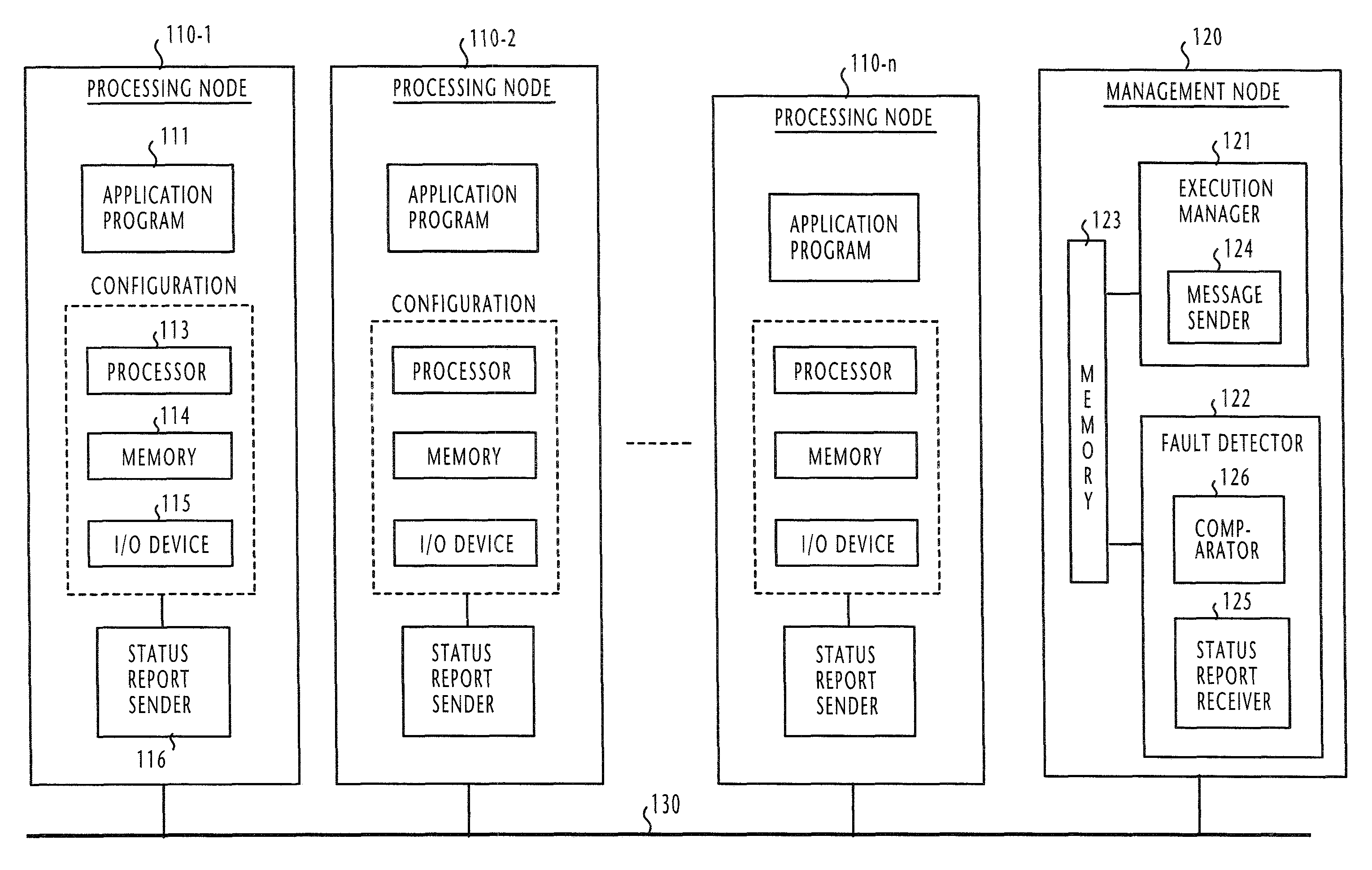
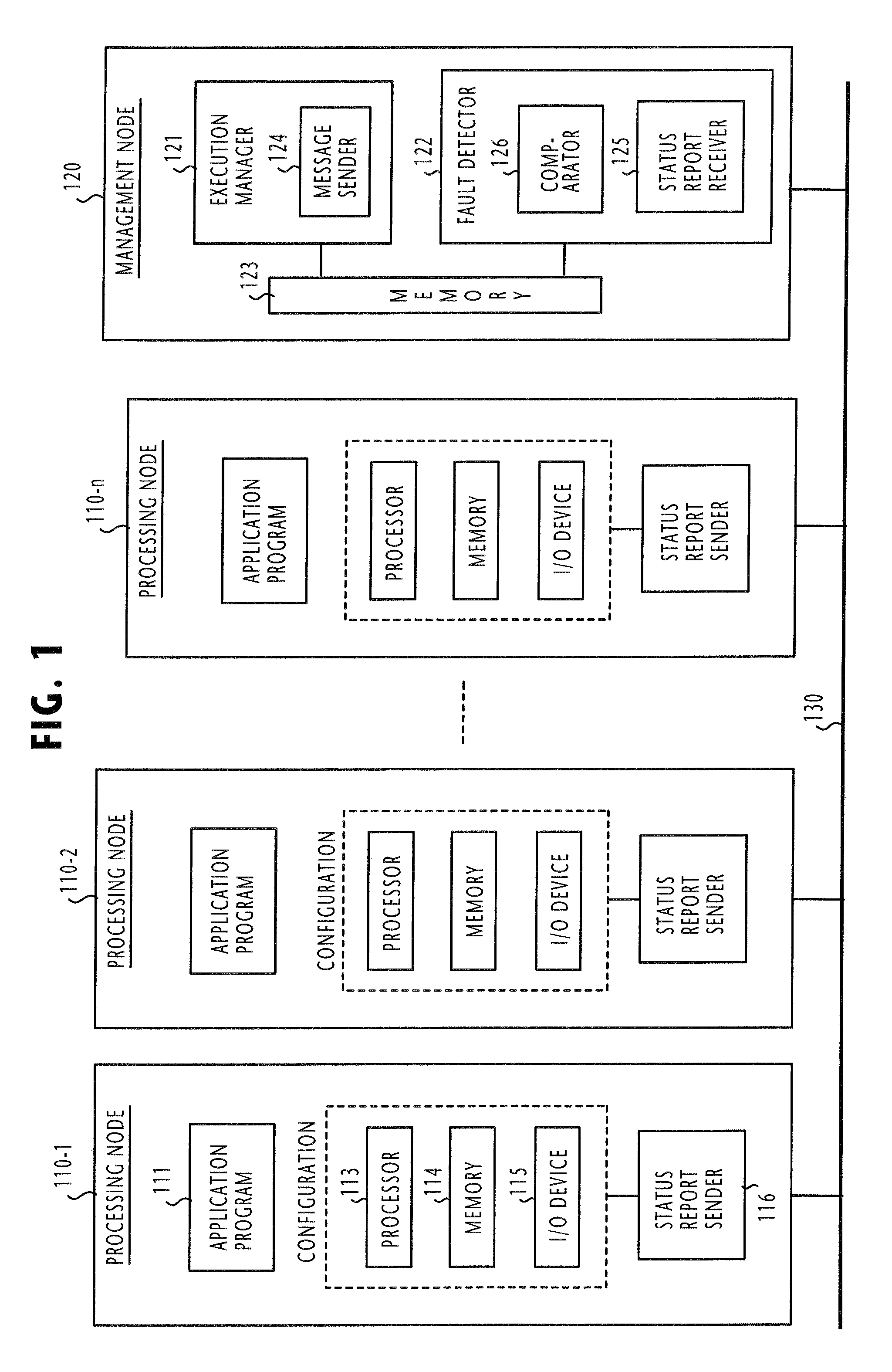
[0037]Referring to FIG. 1, there is shown a fault tolerant parallel-running computing system according to the present invention. The computing system comprises a plurality of processing nodes 110-1˜110-n and a management node 120. All processing nodes and the management node are inter-connected via a common communication medium 130 which may be a serial or parallel bus, wireline or wireless LAN, WAN, the Internet or a public switched network, or a combination of theses. Each of the processing nodes 110 comprises a processor 113, a memory 114 and an input / output device 115, all of which are combined to form an operational environment, or configuration.

[0038]An application program 111 is installed in each processing node. For operating the processing nodes in a parallel running mode, the application programs 111 of all processing nodes are identical to each other in terms of functionality, but are uniquely different from every other nodes in terms of software version number.

[0039]In e...

second embodiment

[0157]FIG. 5 shows the present invention which differs from the previous embodiment in that the execution manager 121 includes a stop command sender 501, instead of or in addition to the message sender 124 of FIG. 1.

[0158]According to the second embodiment of the present invention, the execution manager 121 of FIG. 5 repeatedly executes the routine of FIG. 6 at periodic intervals. In each routine, the execution manager 121 starts with decision step 601 to determine if more than a predetermined number of processing nodes are operating. If not, flow proceeds to the end of the routine. If the decision is affirmative at step 601, flow proceeds to step 602 to fetch configuration items from all operating processing nodes and stores the fetched data in the memory 123. At step 603, the comparator 123 reads the stored configuration status data from the memory 123 and verifies the status data by comparisons between each node and every other node in the same manner as described above. If the c...

third embodiment

[0160]FIG. 7 shows the present invention which differs from the previous embodiment in that the execution manager 121 includes a reconfiguration manager 701. In this embodiment, the memory 123 stores information indicating the number of processing nodes that can be incorporated into the system for parallel run operation, the configuration data of such processing nodes, and the number of currently operating processing nodes.

[0161]According to the third embodiment of the present invention, the execution manager 121 of FIG. 7 repeatedly executes the routine of FIG. 8 at periodic intervals. In each routine of FIG. 8, the execution manager 121 of FIG. 7 begins with step 801 to fetch configuration items from all operating processing nodes and stores the fetched data in the memory 123. At step 802, the comparator 125 reads the stored configuration status data from the memory 123 and compares the status data item-by-item between each node and every other node. If the comparator 125 detects ...


PUM


Abstract

A fault tolerant computing system comprises a plurality of processing nodes interconnected by a communication medium for parallel-running identical application programs. A fault detector is connected to the processing nodes via the communication medium for periodically collecting configuration status data from the processing nodes and mutually verifying the collected configuration status data for detecting an abnormal node. In one preferred embodiment of this invention, the system operates in a version diversity mode in which the processing nodes are configured in a substantially equal configuration and the application programs are identical programs of uniquely different software versions. In a second preferred embodiment, the system operates in a configuration diversity mode in which the processing nodes are respectively configured in uniquely different configurations. The configurations of the processing nodes are sufficiently different from each other that a software fault is not simultaneously activated by the processing nodes.

Description

BACKGROUND OF THE INVENTION[0001]1. Field of the Invention[0002]The present invention relates generally to a multi-node computing system and more specifically to a software-fault tolerant multi-node computing system and a method of enhancing the fault tolerance of a computing system at the level of its software element.[0003]2. Description of the Related Art[0004]Fault tolerant computing systems are known in the computer technology to cope with a system error. Usually, the fault tolerant computing system is one in which a plurality of identical modules are connected to a common bus. All applications are divided into a number of tasks of suitable size and each module is assigned the same task. All the tasks are simultaneously executed by the modules. Through the common bus, each module reads the result of the execution performed by other modules to which the same tasks are assigned and takes a majority decision for masking a system error of any of these modules. However, the presence...

Claims


Application Information

Patent Timeline
Patent Type & Authority Patents(United States)
IPC IPC(8): G06F11/00G06F11/18G06F11/16G06F15/177H02H3/05
CPCG06F11/1641G06F11/1482G06F11/006G06F2201/815
Inventor FUJIYAMA, KENICHIRONAKAMURA, NOBUTATSU
Owner NEC CORP
Why Eureka
Try Eureka