Clamping device for coaxially coupling optical devices

a coaxial coupling and optical device technology, applied in the direction of scaffold accessories, light support devices, washstands, etc., can solve the problems of limitation of the foregoing parameters, the use of conventional telescopic riflescopes in low-light level conditions, and the inability to use typical night vision riflescopes in dayligh

Inactive Publication Date: 2011-01-18
BUSHNELL
View PDF33 Cites 28 Cited by
  • Summary
  • Abstract
  • Description
  • Claims
  • Application Information

AI Technical Summary

Benefits of technology

[0022]Another object of the invention is to provide a clamping device for coaxially coupling an optical accessory device such as a night vision scope to a riflescope, thereby enabling the riflescope to be used in low ambient light conditions.
[0027]Another object of the invention is to provide a clamping device for coaxially coupling an optical accessory such as a night vision device to a riflescope, the clamping device having a front mounting collar which has a front entrance bore for receiving rearwardly therein a rearwardly projecting ocular barrel of a riflescope, the front mounting collar having a releasable clamping mechanism for clamping the riflescope ocular barrel coaxially within the entrance bore of the collar, and a rear mounting ring and support arm assembly which is fastened to the front mounting collar by a pivotable joint which enables the rear mounting ring and arm assembly to be pivoted from a releasably latched orientation rearward of and in coaxial alignment with the front mounting collar, to an unlatched orientation in which the assembly is pivotable about a pivot axle attached tangentially to an outer circumferential surface of the front mounting collar, whereby an optical accessary device held coaxially within a rear entrance bore of the rear mounting ring, and supported thereat by an accessory device support arm which protrudes rearwardly from an outer surface of the rear mounting ring and is releasably attached to an outer surface of the night vision device, is latchable into coaxial alignment with a riflescope to which the clamping device is attached, thereby enabling optically coupled usage of the riflescope and accessory optical device, and, upon unlatching a latchable fastener joint joining the rear mounting ring and arm assembly to the front mounting collar, the rear mounting ring, arm, and attached accessary optical device are pivotable away from the front mounting ring and riflescope, thereby enabling direct viewing through the riflescope.
[0030]Briefly stated, the present invention comprehends clamping devices for releasably coupling a pair of longitudinally arranged optical devices in coaxial alignment with one another. A primary intended use for clamping devices according to the present invention is the temporary coupling of an optical accessary device such as a night vision scope to a telescopic rifle sight or riflescope, with the accessory device located behind and in coaxial alignment with the riflescope. In particular, clamping devices according to the present invention are useful for temporarily coupling a night vision device, such as an infrared image converter or image intensifier, to the eyepiece or ocular end of a riflescope mounted on a rifle, thus enabling the riflescope to be used at night or in other low ambient light-level environments with the night vision device attached by the coupler to the riflescope, and the riflescope quickly and interchangeably restorable to a daylight use configuration by removing the night vision device from coaxial alignment with the riflescope.
[0033]The clamp arms have disposed transversely and perpendicularly therethrough a pair of opposed bores which insertably receive the shank of a clamp thumbscrew. Tightening the thumbscrew against one clamp arm by turning a shank fixed to the thumbscrew knob within threads within the bores of either or both clamp arm bores, or within an internal threaded bore of a knurled thumbscrew knob, causes a screw head on the opposite end of the shank to be drawn compressively into contact with the outer face of the opposite clamp arm, thus drawing opposed inner longitudinally and radially disposed faces of the clamp arms towards one another. In another arrangement, the thumbscrew knob is internally threaded and tightened on the shank of the screw. Since the opposed clamp arms are integral with opposed split collar halves, tightening the clamp thumbscrew causes the inner cylindrical wall surfaces of the split collar halves to be deformed circumferentially inwards, thus reducing an inner diameter of the split collar bore and thereby causing the semi-cylindrically-shaped split collar halves to exert a radially inwardly directed, compressive clamping force on the outer cylindrical wall surface of a cylindrical object, such as the tubular eye piece tube of a telescopic rifle sight, which has been inserted into the bore with the clamp arms in a loosened, spaced apart arrangement.
[0037]The above-described clamping device also includes latching means for securing a night vision device from longitudinal movement relative to the rear mounting ring, after the mounting bosses have been slid forward into the device support arm channels. In a preferred embodiment, the latching means includes within each support arm channel, near a rear end thereof, a pivotable spring-biased pawl which has an inwardly projecting end that is biased by a compression spring inwardly towards a vertical center plane of the mounting ring. When the front obliquely rearwardly angled vertical edge wall of a front boss contacts the pawl, the pawl is pivoted resiliently outwardly, allowing the front and rear bosses to move longitudinally forwards sufficiently far for the front transverse edge of the objective lens tube of the night vision device to be seated within the rear mounting ring. When the night vision device is pushed sufficiently far forward for it to be fully installed within the rear mounting ring, the latching pawls spring resiliently inwards into latching engagement with rear straight vertical edges of the front bosses. The pawls are releasable by pressing inwardly on the outer end of a lever arm which protrudes outwardly from a rear end portion of each pawl that protrudes obliquely outwards from an outer rear end of each arm, using a thumb and forefinger, for example, thus pivoting the pawls outwards and enabling the night vision scope to be withdrawn rearwardly from the mounting arm channels and rear mounting ring.
[0041]The pivot axle within the pivot axle support boss has a first, latched, zero-degree azimuthal angle position in which the optical device support arm is disposed parallel to the longitudinal axis of the front clamping assembly and rearward therefrom, to thereby position a viewing device supported by the arm rearward of and in coaxial alignment with the riflescope. The pivot axle is also rotatable 180 degrees counterclockwise to a second, latched 180-degree azimuthal angle to thereby position the optical device support arm and attached optical device to a forward direction parallel to and along side the riflescope, thus allowing direct viewing through the riflescope.

Problems solved by technology

Magnification of a target image using a typical riflescope substantially increases the range over which an average shooter can accurately fire on a target, as compared to the shooters use of mechanical sights which do not employ magnifying lenses, i.e., “iron sights.” However, the use of conventional telescopic riflescopes under low-light level conditions, e.g., at dusk or dawn, can be problematic for the following reasons.
Although a riflescope can in principle utilize any combination of magnifying power and objective lens size, practical considerations such as size and weight place limits on the foregoing parameters.
It should be noted that a typical night vision riflescope cannot be used during daylight conditions because the high light amplification of such devices results in overly bright, low contrast image under normal ambient lighting conditions.
Also, some low-light level devices can be permanently damaged by normal levels of illumination.

Method used


Image

  • Clamping device for coaxially coupling optical devices
  • Clamping device for coaxially coupling optical devices
  • Clamping device for coaxially coupling optical devices

Examples


Embodiment Construction

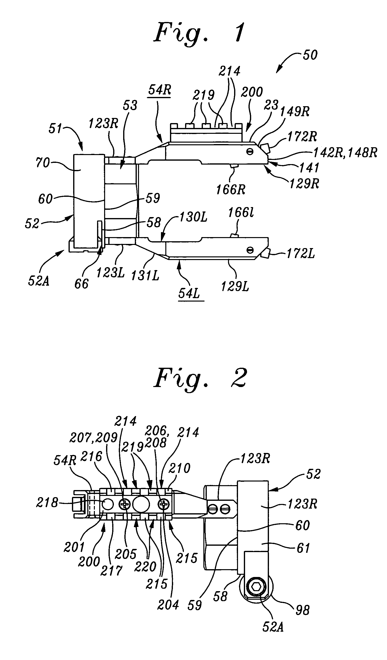
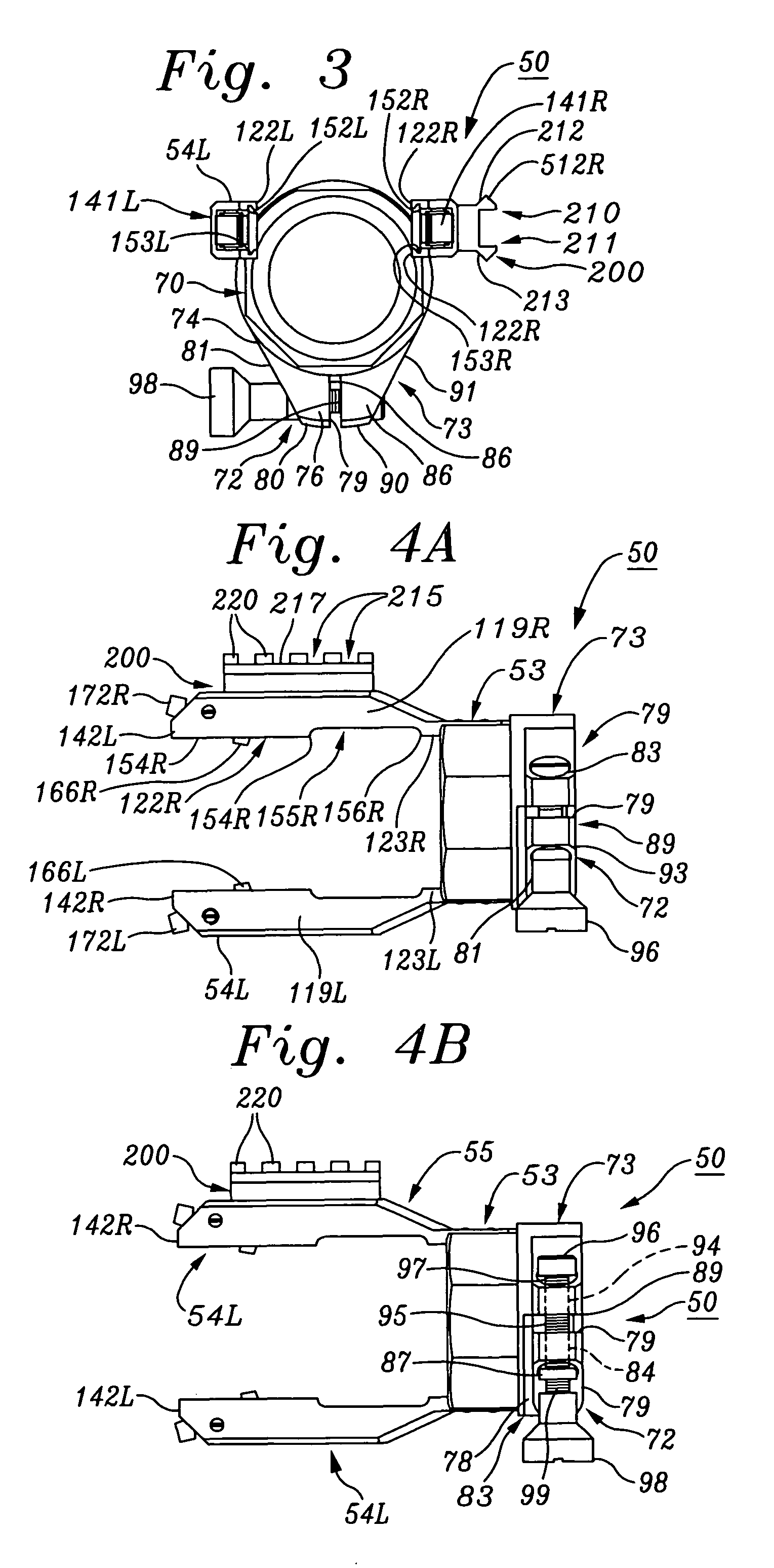
[0096]FIGS. 1-17 illustrate a basic, double-arm embodiment of a clamping device for coaxially coupling optical viewing devices to riflescopes, according to the present invention. FIGS. 18-29 illustrate a single-arm, swing-away embodiment of the invention. FIGS. 30-32 illustrate a modification of the swing-away embodiment of the invention.

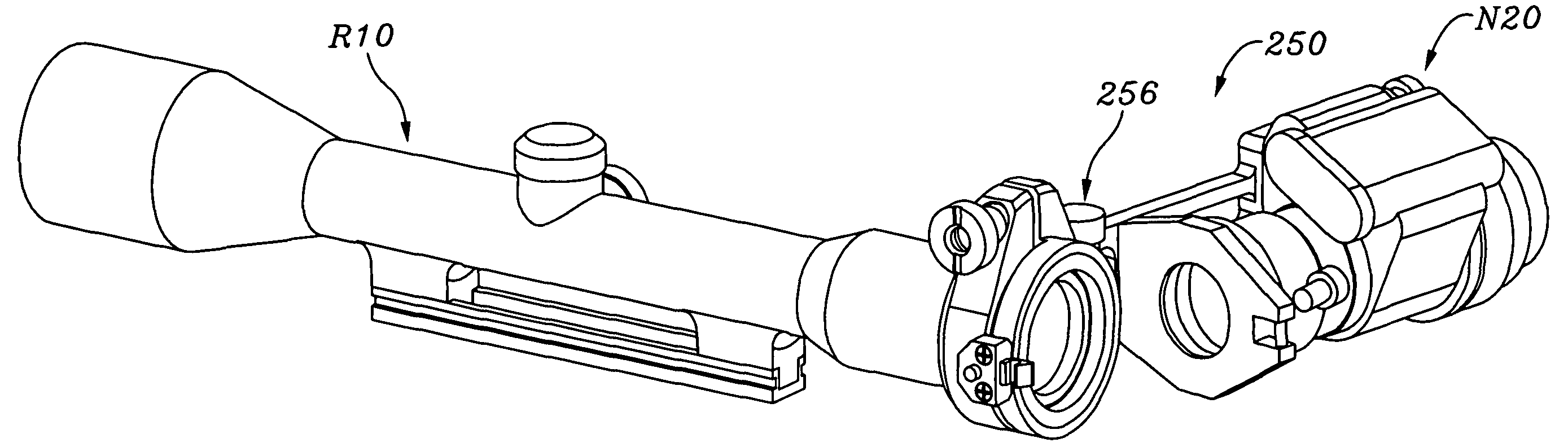
[0097]Referring first to FIGS. 1-7, a basic embodiment 50 of a clamping device or coupler for coaxially coupling optical devices to riflescopes according to the present invention may be seen to include a split front mounting collar 51 which is adapted to coaxially receive the rear, ocular or eyepiece tube of a riflescope, and a front clamp assembly 52A which secures the eyepiece tube within a split collar 61. Coupler 50 also includes a rear tubular mounting ring 53 which protrudes rearwardly from and is coaxially aligned with front mounting collar 51 and front clamp assembly 52A. Rear tubular mounting ring 53 is adapted to coaxially receive the tubu...


PUM


Abstract

A clamping device for coupling optical devices in coaxial, tandem alignment includes a front clamp assembly that has elastically deformable split collar halves tightenable onto a front optical device by a screw tightenable into bores disposed transversely through a pair of arms extending radially from the split collar halves. A rear optical device support protrudes rearward from the front clamp assembly, and has a releasable fastener such as a screw or dovetail joint for supporting a rear optical device in coaxial alignment with the front optical device. Preferably, the arm is mounted to the front clamp assembly by means of a pivotable joint which is latchable in a first, rearward position, and a second, forward position in which the rear optical device is positioned along the side of the front optical device, so that the front device may be used independently of the rear device.

Description

BACKGROUND OF THE INVENTION[0001]A. Field of the Invention[0002]The present invention relates to devices for coupling together a pair of optical devices, such as a night-vision device to a telescopic sight mounted on a rifle. More particularly, the invention relates to a versatile clamping device for releasably and coaxially coupling an auxiliary optical device such as an infrared viewer, image intensifier, or other such night vision device used to enhance viewability of objects in dark environments, to a riflescope of the type useful primarily for daylight conditions, thus adapting the riflescope for nighttime use.[0003]B. Description of Background Art.[0004]A typical riflescope of the type used by hunters, law enforcement personal, and members of the military, comprises essentially a Galilean telescope which is provided with an internal sighting reticle. Most riflescopes have a longitudinally elongated, main tube, a short, front tubular objective lens assembly of a larger diameter...

Claims


Application Information

Patent Timeline
Patent Type & Authority Patents(United States)
IPC IPC(8): F41G1/38
CPCF41G11/004
Inventor DASIUKEVICH, VLADIMIR
Owner BUSHNELL
Why Eureka
Try Eureka