V-shaped product conveyor

a conveyor and product technology, applied in the direction of conveyor parts, rollers, rollers, etc., can solve the problems that the conventional conveyor system is not always designed for comfort, and achieve the effect of high profile and easy adjustmen

Inactive Publication Date: 2011-01-18
RINNE RHETT L
View PDF16 Cites 0 Cited by
  • Summary
  • Abstract
  • Description
  • Claims
  • Application Information

AI Technical Summary

Benefits of technology

[0013]The use of the letter “V” in describing the novel structure has several advantages. First of all, the left side of the “V” may be thought of as the passive side of the conveyor structure that supports a product container that has been knocked over to its left, its bottom wall no longer sitting squarely atop a level support surface. The right side is then thought of as the active side. It includes the driving means that causes movement of the product container along a path of travel. The tilted bottom wall of the package is drivingly engaged by the right side of the “V”-shaped conveyor structure. Instead of left and right, or passive and active, the opposing sides of the “V”-shaped structure may also be referred to as rearward and forward.
[0014]The passive or rearward side of the structure may include rotatably mounted wheels that are positioned along the extent of the conveyor structure to facilitate the work of the active or forward side of the novel apparatus by reducing the resistance to movement of the product container. The passive side may also include an elongate rail against which the product container leans as it is driven along its path of travel by the active side of the apparatus. A rail may produce more friction but a structure having a rail that supplants multiple wheels is less expensive to make and maintain.
[0017]More particularly, a first embodiment includes a pair of longitudinally spaced apart posts, each surmounted by a pair of rearward and forward support arms that collectively form a lower case “v.” A rearward primary support rail interconnects respective distal ends of the rearward support arms and slidingly supports a product container. Alternatively, a plurality of passive support wheels may be rotatably mounted along the extent of the rail to reduce the friction that must be overcome to transport the product container. Each passive support wheel is rotatable about an axis substantially perpendicular to the rearward primary support rail. A conveyor belt or equivalent driving structure is mounted on the forward side of the structure. This first embodiment is all that is needed to convey a product container having a size that fits such structure, i.e., having a low profile and a narrow width.
[0020]A fourth embodiment has the same structure as the second, but an extension is secured to each forward support arm, in effect lengthening each forward support arm. A secondary forward support rail connects contiguous distal ends of the forward extensions. A plurality of passive rotatably mounted wheels may be mounted along the extent of the secondary forward support rail, or said rail may itself be used to passively, slidingly support a product container in the absence of such wheels. This fourth embodiment enables the conveyance of a product container having a large width and a tall profile.
[0025]Another important object is to provide a conveyor system that is easily adjustable to handle product containers having a narrow width and a low profile, a narrow width and a high profile, a broad width and a low profile, and a broad width and a high profile.

Problems solved by technology

Conventional conveyor systems are not always designed for the comfort of the workers who load and unload the product.

Method used


Image

  • V-shaped product conveyor
  • V-shaped product conveyor
  • V-shaped product conveyor

Examples


fourth embodiment

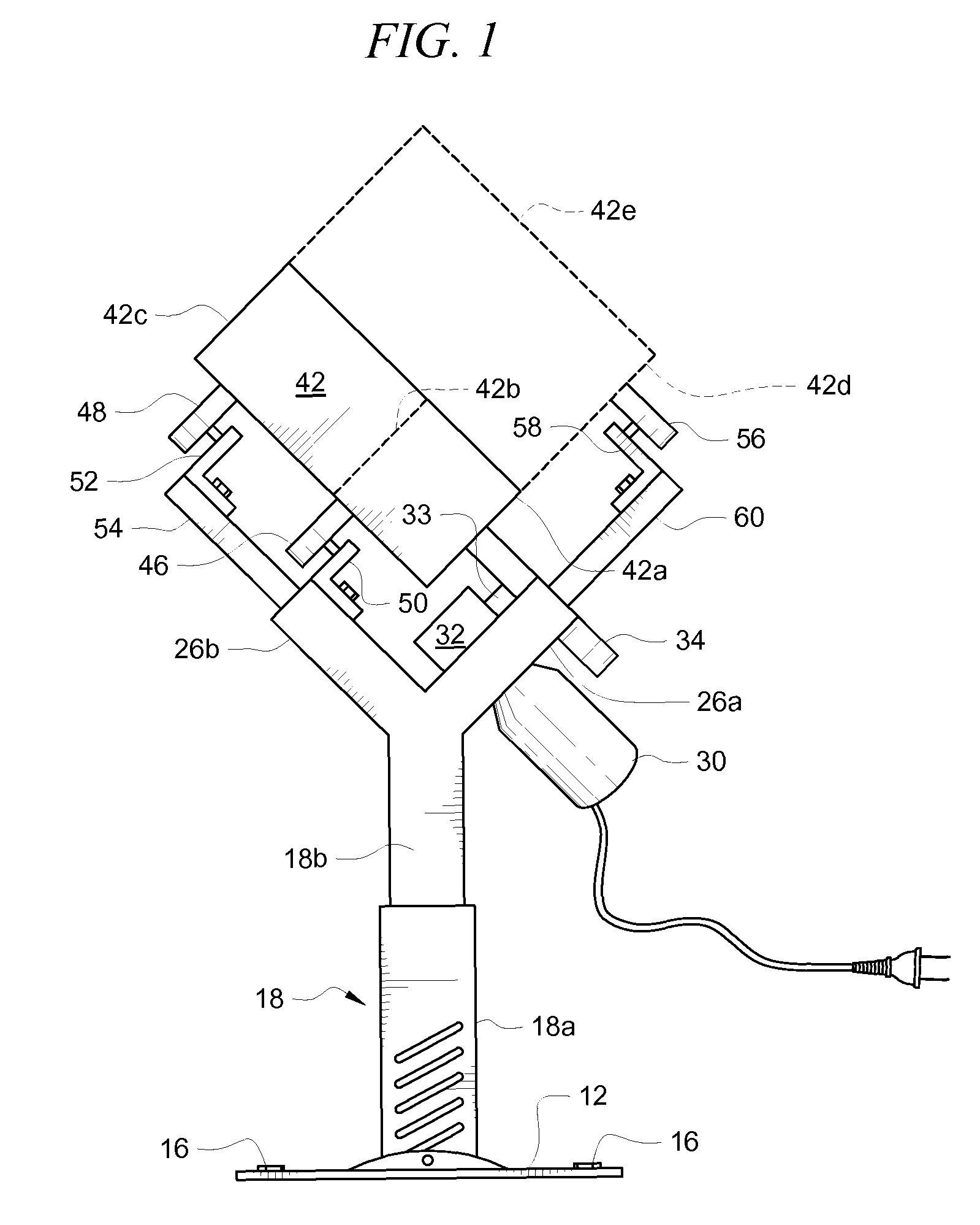
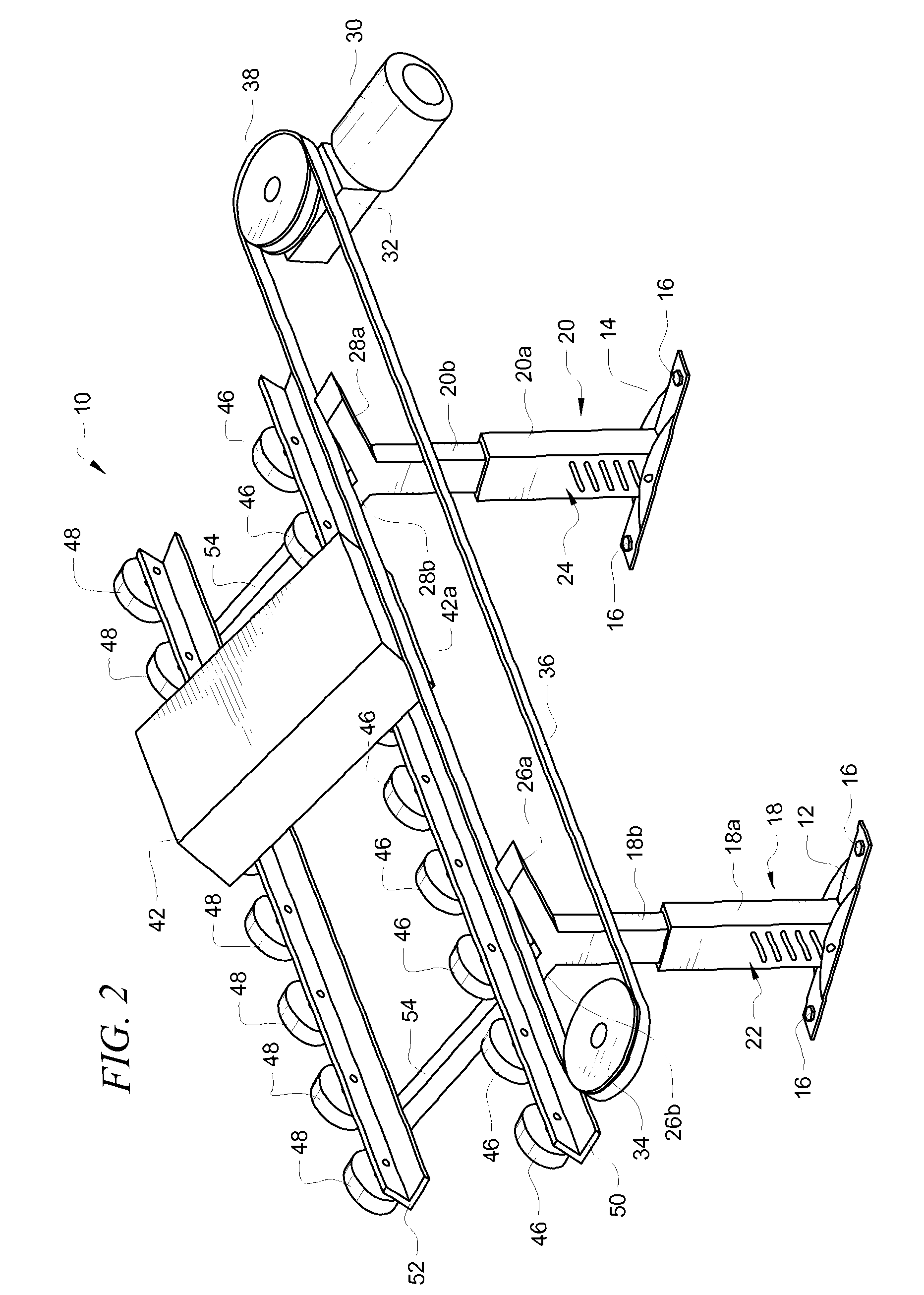
[0041]FIG. 2 is a view of the invention but it may be interpreted as a composite view that includes the first three embodiments as well.

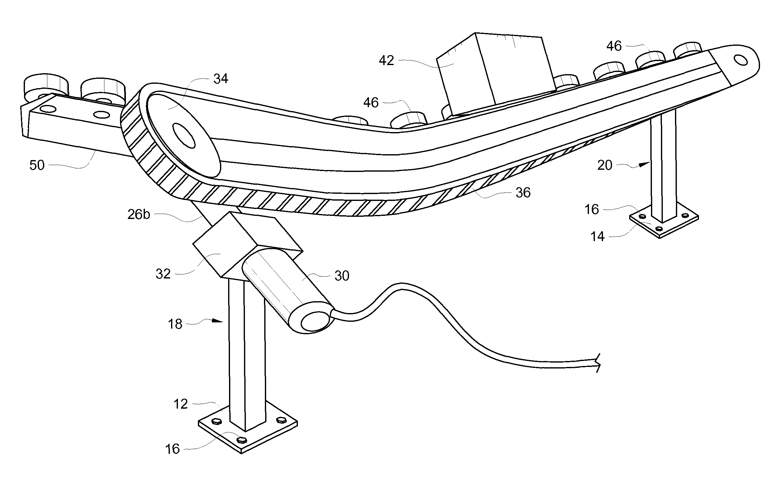
[0042]Only the short-short structure of the first embodiment is employed when product container 42 is small, i.e., relatively narrow in width and low in height. Bottom wall 42a in solid lines of such container is actively supported by drive means 36 only. Reference numeral 42b indicates the top wall of such low profile, narrow width container. The unnumbered side wall of said small product container is passively supported by a plurality of primary passive rollers or wheels 46 that are mounted to longitudinally-extending rearward primary support rail 50. As mentioned above, this first embodiment also contemplates the elimination of wheels 46 and the use of rail 50, properly re-positioned, as the passive support means for the product container.

[0043]Only the long-short structure of the second embodiment is employed when product container 42 is relativ...

second embodiment

[0052]Corners include, on a first side, a driven band, rope, belt, chain, driven wheel, or the like, and on a second, opposite side, balls, rollers, plates, wheels, rails, or various combinations thereof. FIGS. 5 and 6 depict a product container negotiating a corner. It will be noted that said Figs. depict the long-short or second embodiment of the invention. Turning cone 80 is mounted to bracket 82 that is mounted to secondary passive support rail 52. Product container 42 will continue to travel in a straight direction when the system is in its FIG. 5 configuration but it will negotiate a ninety degree (90°) turn when in its FIG. 6 configuration. Note in FIG. 6 that a section of rearward primary support rail 50 is hingedly mounted so that it can swing into the FIG. 6 position. When said section 50 is upraised, turning cone 80 deflects product container 42 onto the conveyor structure disposed ninety degrees (90°) to the main conveyor section.


PUM


Abstract

A conveyor system includes first and second upstanding posts disposed in longitudinally spaced apart relation to one another. Each post is surmounted by forward and rearward support arms that form a “V”-shape. A forward drive belt is mounted for rotation along a path of travel perpendicular to the forward support arms. A first embodiment cradles a product container between the forward drive belt and a rearward primary support arm. A second embodiment includes the first embodiment structure and adds a rearward secondary support arm. A third embodiment includes the primary but not the rearward secondary support arm, the forward drive belt and a forward secondary support arm. A fourth embodiment includes the rearward primary and secondary support arms, the forward drive belt and a forward secondary support arm. The product container is tilted from vertical so that the conveyor follows a path of travel including curvatures having no guide rails.

Description

BACKGROUND OF THE INVENTION[0001]1. Field of the Invention[0002]This invention relates to product conveyors. More particularly, it relates to a conveyor system that eliminates or reduces the use of guide rails.[0003]2. Description of the Prior Art[0004]Conventional conveyor systems carry product containers on flat, level belts or other driving surfaces. When the path of travel includes a curvature, guide means are provided so that the product container will encounter such guide means and be deflected thereby onto a changed path of travel. Curvatures of lengthy extent thus require more guide rails than shorter curvatures.[0005]Thus there is a need for a conveyor system that can follow a path of travel that includes curves but which does not require guide rails.[0006]Conventional conveyor systems are not always designed for the comfort of the workers who load and unload the product.[0007]There is a need as well to convey products that are positioned ergonomically relative to workers w...

Claims


Application Information

Patent Timeline
Patent Type & Authority Patents(United States)
IPC IPC(8): B65G15/60
CPCB65G13/11B65G19/306B65G21/2054B65G47/54B65G47/66B65G2201/025
Inventor RINNE, RHETT L.
Owner RINNE RHETT L
Why Eureka
Try Eureka