Antenna apparatus utilizing aperture of transmission line

an antenna and transmission line technology, applied in the direction of antennas, electrically short antennas, antenna feed intermediates, etc., can solve the problems of difficult long distance communication, and achieve the effect of large antenna gain and communication

Active Publication Date: 2011-01-18
RENESAS ELECTRONICS CORP +9
View PDF20 Cites 0 Cited by
  • Summary
  • Abstract
  • Description
  • Claims
  • Application Information

AI Technical Summary

Benefits of technology

[0011]An object of the present invention is to solve the above-mentioned problems and provide an antenna apparatus, that is connected to a transmission line and has a simple configuration and a directivity of almost no change in frequency characteristics, and that is capable of performing communications even at a comparatively long distance.
[0022]Accordingly, the antenna apparatus utilizing the aperture of transmission line according to the present invention is connected to the transmission line, and has a configuration much simpler than that of the prior art and a narrow directivity with almost no change in frequency characteristics, thereby making it possible to achieve a large antenna gain and to perform communications even at a comparatively long distance.

Problems solved by technology

Furthermore, the group waves are heavily attenuated even in the air at high frequencies in the bands equal to or higher than GHz band and become a level, that is larger than such an attenuation theorem at lower frequencies that the energy becomes weak in inverse proportion to the square of the distance (because of expansion in a spherical shape), and that is in inverse proportion to the cube of the distance by approximation, and this leads to that it is difficult to perform long distance communications.

Method used


Image

  • Antenna apparatus utilizing aperture of transmission line
  • Antenna apparatus utilizing aperture of transmission line
  • Antenna apparatus utilizing aperture of transmission line

Examples


Embodiment Construction

[0073]Preferred embodiments of the present invention will be described below with reference to the drawings. In each of the following preferred embodiments, like components are denoted by like reference numerals.

[0074]The present invention is derived from a fundamental principle quite different from that of the antenna that resonates at a specified frequency such as a dipole antenna, and has a theoretically novel configuration as described in detail below.

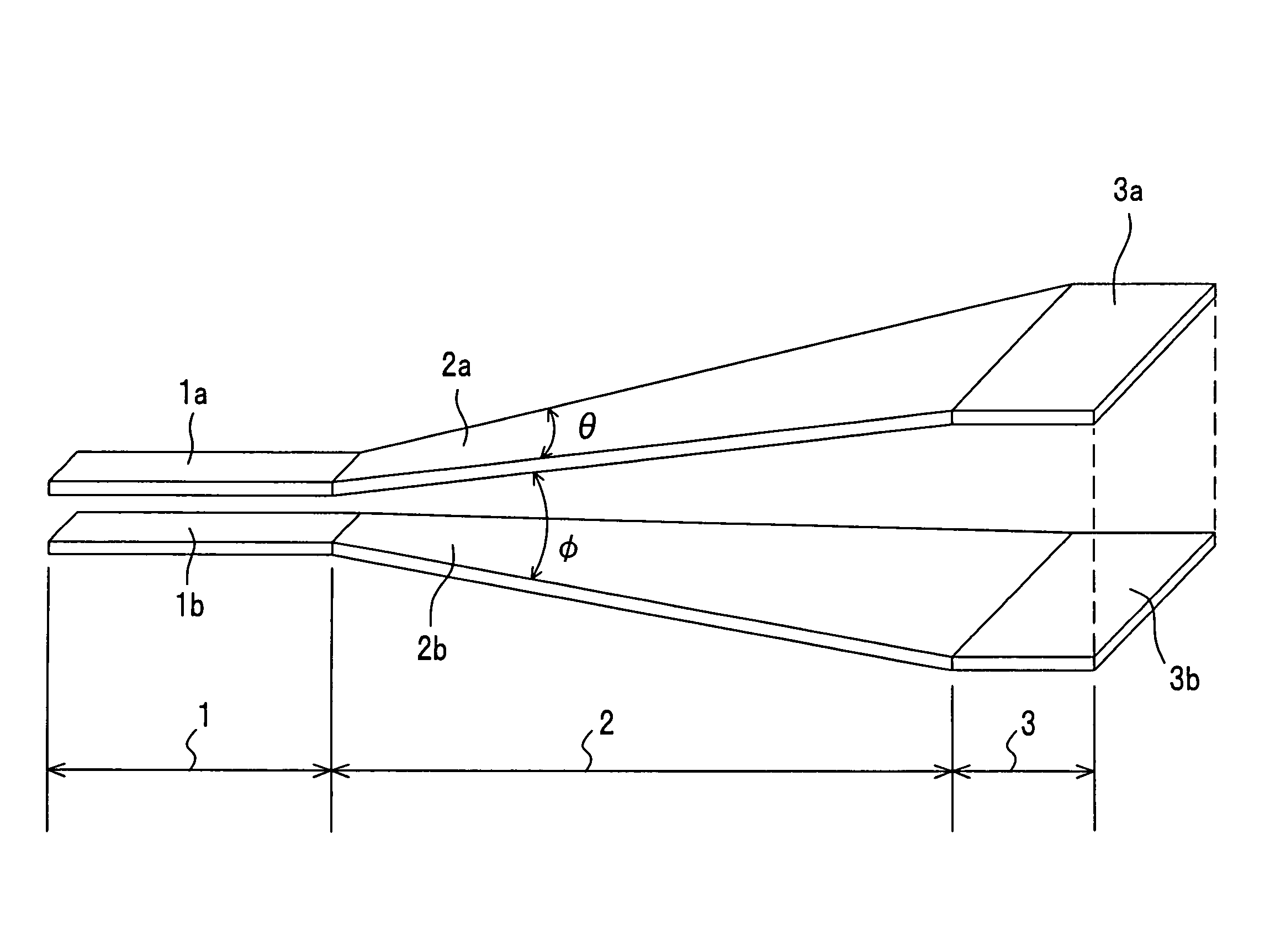
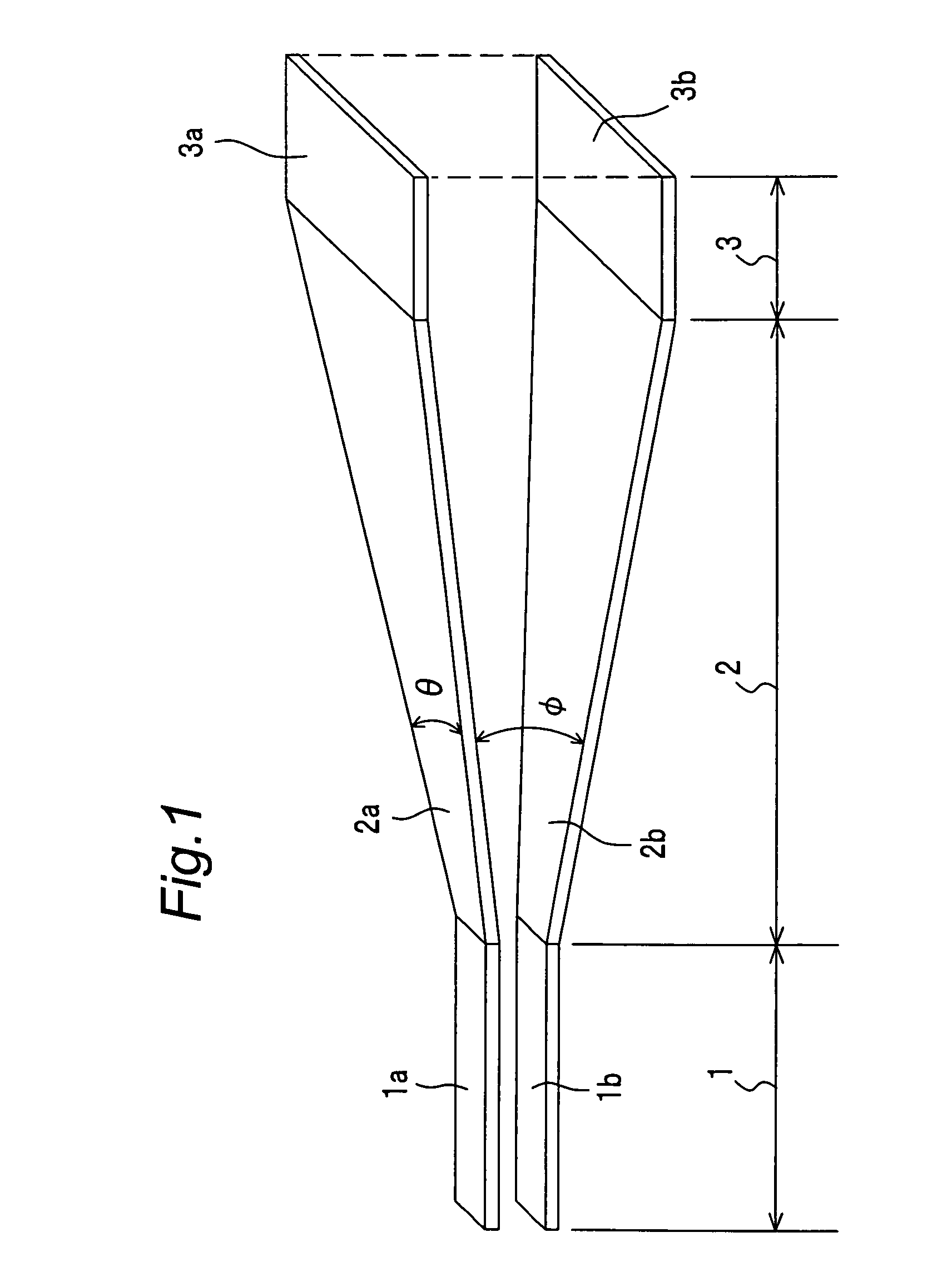
[0075]FIG. 1 is a perspective view showing an appearance of the antenna apparatus utilizing the aperture of transmission line according to the first preferred embodiment of the present invention. The antenna apparatus utilizing the aperture of transmission line of the first preferred embodiment is connected to a stacked pair line 1 including a pair of line conductors 1a and 1b each having a predetermined characteristic impedance such as 50Ω, where a pair of line conductors 1a and 1b oppose to each other.

[0076]The antenna apparatus ...


PUM


Abstract

An antenna apparatus utilizing an aperture of transmission line, which is connected to a first transmission line having a predetermined characteristic impedance, includes a tapered line portion, and an aperture portion. The tapered line portion is connected to one end of the transmission line, and the tapered line portion includes a second transmission line including a pair of line conductors. The tapered line portion keeps a predetermined characteristic impedance constant and expands at least one of a width of the transmission line and an interval in a tapered shape at a predetermined taper angle. The aperture portion has a radiation aperture connected to one end of the tapered line portion. A size of one side of the aperture end plane of the aperture portion is set to be equal to or higher than a quarter wavelength of the minimum operating frequency of the antenna apparatus.

Description

BACKGROUND OF THE INVENTION[0001]1. Field of the Invention[0002]The present invention relates to an antenna apparatus utilizing an aperture of transmission line, and in particular, to an antenna apparatus which can be used in frequency bands such as bands of microwaves, quasi millimeter waves, millimeter waves, or the like.[0003]2. Description of the Related Art[0004]An antenna has been always used in wireless communication systems such as portable telephones. The concept of the conventional antenna has such a structure for resonating at a specified frequency, and a typical dipole antenna resonates at a half of an operating wavelength thereof.[0005]In the dipole antenna, electromagnetic waves having the TM (Transverse Magnetic) mode are generated concentrically around the pole. However, electromagnetic waves that have reached a distance several times the wavelength interfere with one another at the boundary portions thereof, and the electromagnetic wave mode is transformed into TEM ...

Claims


Application Information

Patent Timeline
Patent Type & Authority Patents(United States)
IPC IPC(8): H01Q9/28
CPCH01Q13/06
Inventor OTSUKA, KANJIUSAMI, TAMOTSUAKIYAMA, YUTAKAUEDA, CHIHIRO
Owner RENESAS ELECTRONICS CORP
Why Eureka
Try Eureka