Method and device for detecting the contour data and/or optical characteristics of a three-dimensional semi-transparent object

Active Publication Date: 2011-01-18
DEGUDENT
View PDF20 Cites 92 Cited by
  • Summary
  • Abstract
  • Description
  • Claims
  • Application Information

AI Technical Summary

Benefits of technology

[0030]To improve the signal-disturb signal ratio, it is provided that a large number of frames, that is, the overall image content of the image sensor of a defined period of t

Problems solved by technology

The disadvantage with the described method is that the resolution in the z direction, that is, into the depth of the object, is restricted.
This is thus an additional operation,

Method used


Image

  • Method and device for detecting the contour data and/or optical characteristics of a three-dimensional semi-transparent object
  • Method and device for detecting the contour data and/or optical characteristics of a three-dimensional semi-transparent object
  • Method and device for detecting the contour data and/or optical characteristics of a three-dimensional semi-transparent object

Examples


Embodiment Construction

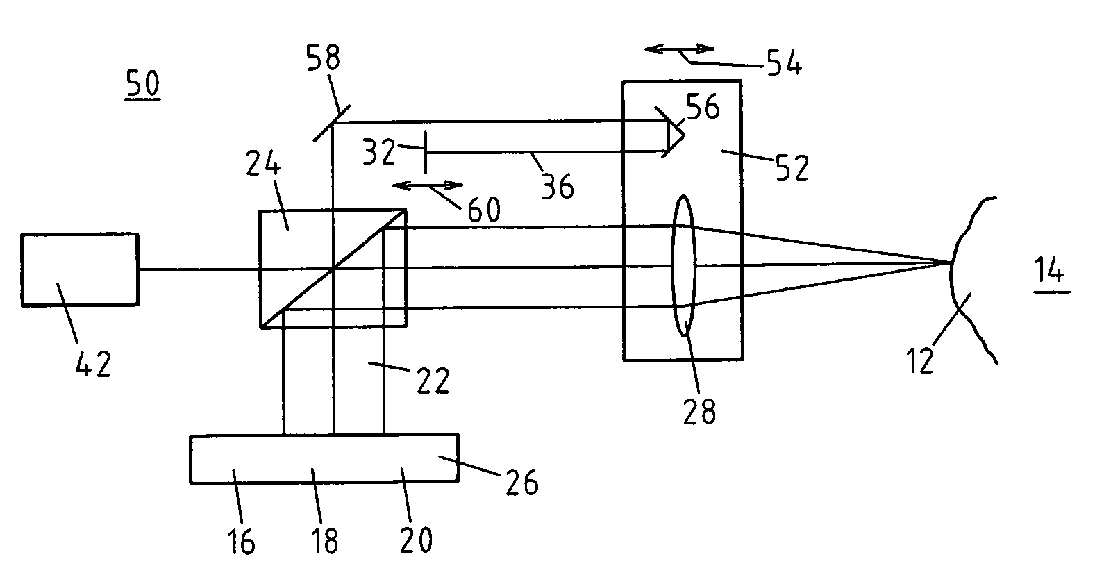
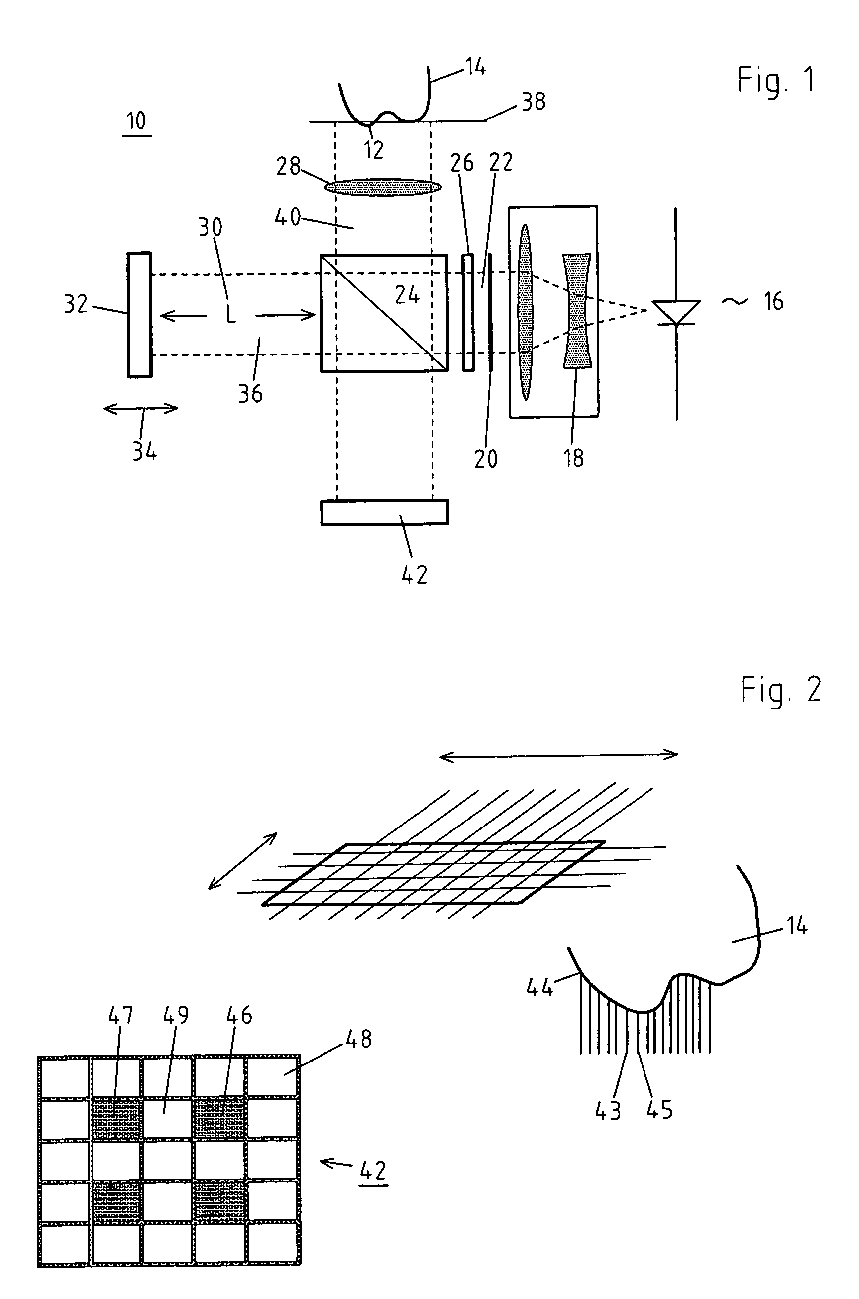
[0053]FIG. 1 illustrates a schematic construction of a device 10 for recording contour data of a free form surface 12 of a semi-transparent object 14.

[0054]The light of a light surface 16 of short coherence length is expanded through a beam expander 18 and projected on a lens array 20 which generates from this a bundle of rays 22 of a large number of individual rays. These run through a beam shifter 26, a beam splitter 24 and through an axially displaceable focusing optical system 28 to the object 14, such as a tooth, whose geometrical data are to be measured.

[0055]The beam shifter 26 serves to shift the bundle of rays 22 by fractions of the distance between the individual rays in order to increase the resolution. In this way, there exists the possibility of shifting the bundle of rays 22, that is its individual light rays overall, with respect to place in order consequently to be able to measure the regions of the object 14 as well which possibly could not be recorded by other impi...


PUM


Abstract

A method and device for detecting the contour data and/or optical characteristics of an object, such as a tooth or a tooth restoration, based on an interference and/or autocorrelation measurement using an image sensor. To permit an exact surface detection in addition to a determination of the optical characteristics of the object, individual light beams strike the object, which are located at a distance from one another in such a way that no impact of reflected individual light beams takes place on immediately adjacent pixels of the image sensor.

Description

BACKGROUND OF THE INVENTION[0001]The invention relates to a method for recording contour data and / or optical properties of a three-dimensional semi-transparent object, especially a semi-transparent object in the dental area, such as a tooth or tooth restoration, on the basis of an interference and / or autocorrelation measurement, whereby[0002]a bundle of rays from at least one light source of short coherence length is generated,[0003]the bundle of rays is passed through a beam splitter and is preferably guided to the object through a focusing optical system,[0004]a reference beam is split off in the beam splitter from the bundle of rays and is reflected by a reference mirror movable along the reference beam, whereby by moving the reference mirror, a position relative to a signal gaining surface is fixed relative to the object, and[0005]the beam reflected from the object and from the reference mirror are brought together in the beam splitter and transferred into an image sensor having...

Claims


Application Information

Patent Timeline
IPC IPC(8): G01B11/24G01B9/02
CPCA61C13/0004G01B11/2441G01N21/49A61C9/0053A61C19/04G01B11/24
Inventor ERTL, THOMAS
Owner DEGUDENT
Why Eureka
Try Eureka