Attachment for ceramic matrix composite component

a composite material and ceramic matrix technology, applied in the direction of fastening means, machines/engines, waterborne vessels, etc., can solve the problems of ceramic components and their connections being subject to wide thermal changes, ceramic components are difficult to attach to metallic components, and ceramic materials cannot be welded to metal

Inactive Publication Date: 2011-01-25
SIEMENS ENERGY INC
View PDF29 Cites 67 Cited by
  • Summary
  • Abstract
  • Description
  • Claims
  • Application Information

AI Technical Summary

Problems solved by technology

In addition, these components and their connections are subject to wide thermal changes during variations in engine operation, including engine shutdowns and restarts.
However, ceramic components are difficult to attach to metallic components.
Ceramic material cannot be welded to metal, and ceramic-metal braze alloys can not withstand the very high temperatures found in gas turbine engines.
Ceramic material differs from metal in thermal conductivity and growth, making it challenging to attach ceramic parts to metal parts in a hot and varying environment.
Thus, attaching CMC components to metal structures with bolts or pins is a challenge.
Fiber bundles (tows) in these fabrics have natural out-of-plane undulations that are essentially pre-buckled, and are sites for premature failure under compressive loads.
Current oxide-based CMCs have low interlaminar tensile strength, which limits compressive strength.
Such stresses are sufficient to cause local damage in the CMC and initiate other modes of failure, such as shear tear-out.
Pin-loaded hole tests also show that local damage in the contact zone can result in local delamination and subsequent propagation of damage.

Method used


Image

  • Attachment for ceramic matrix composite component
  • Attachment for ceramic matrix composite component
  • Attachment for ceramic matrix composite component

Examples


Embodiment Construction

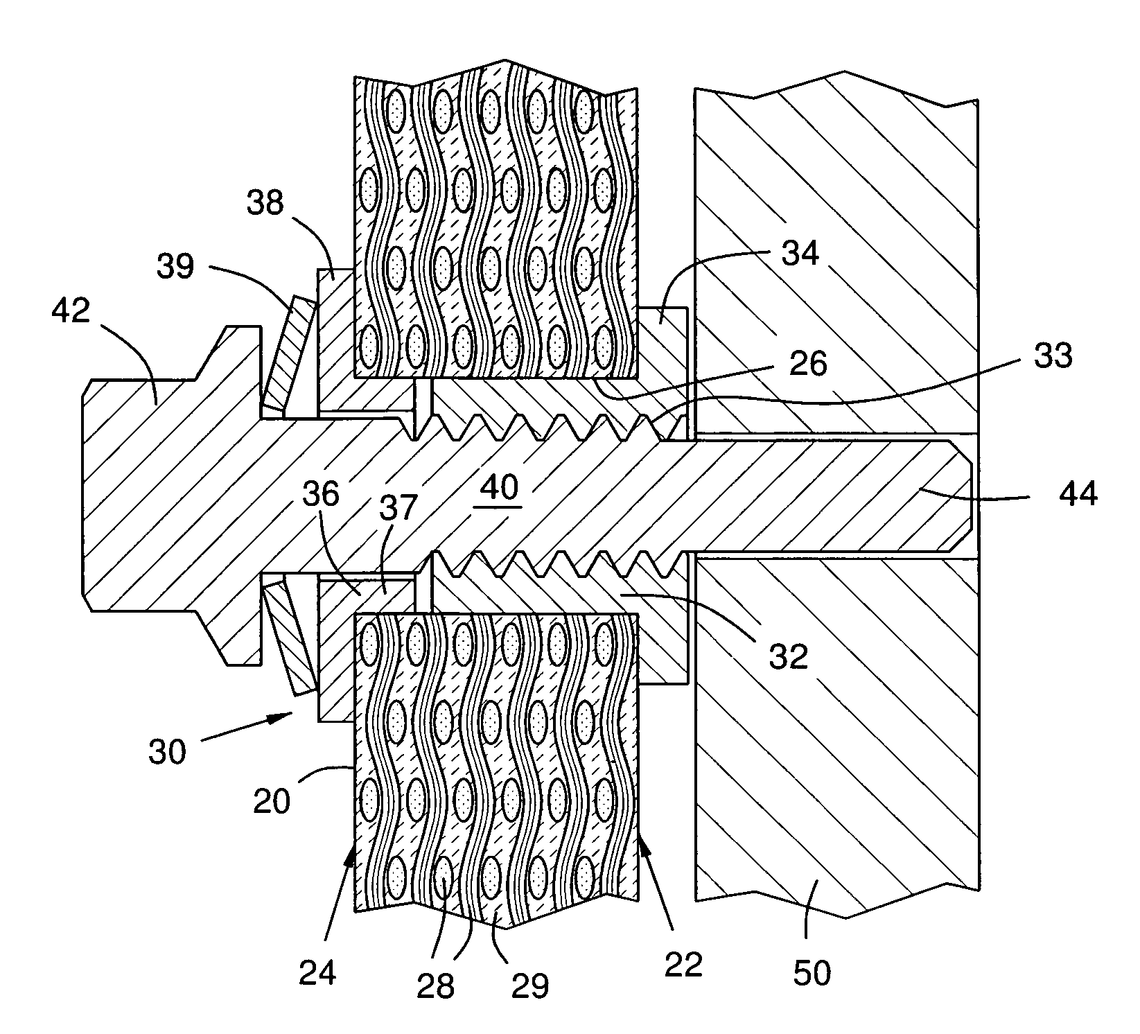
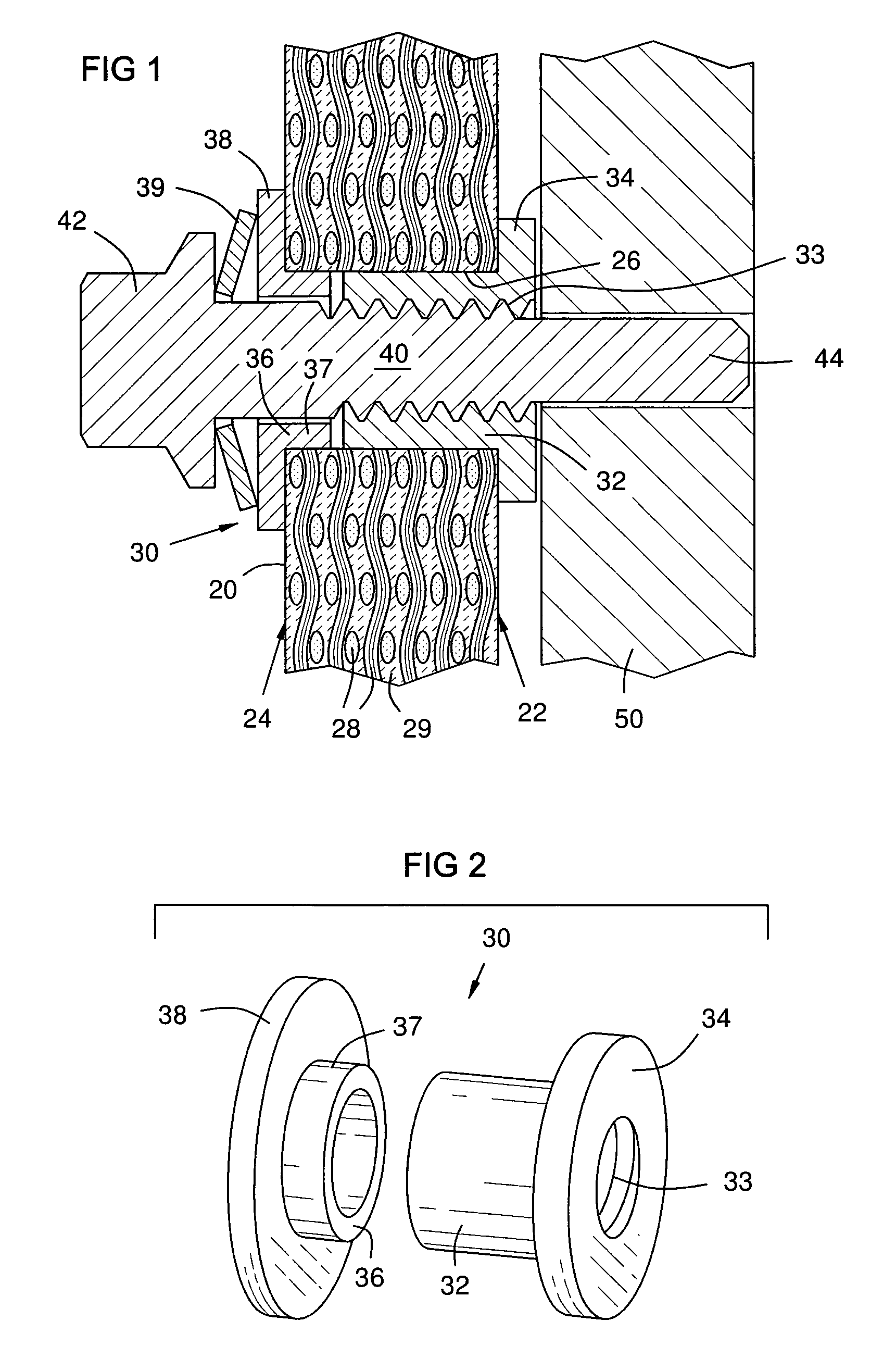
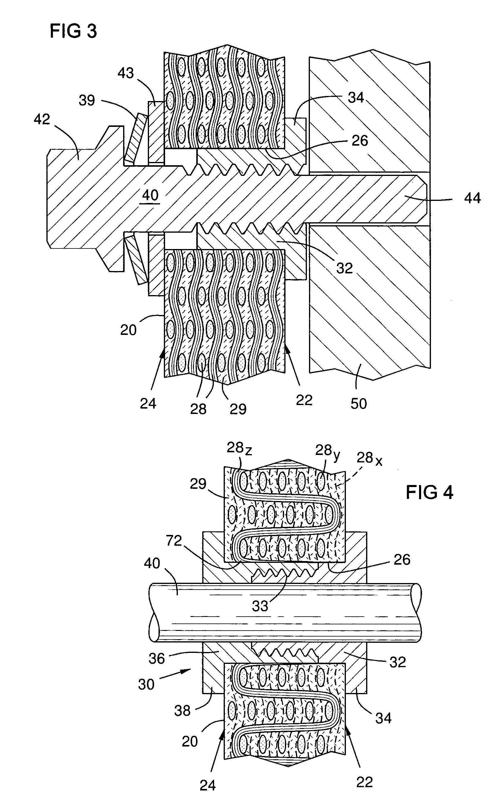
[0015]FIG. 1 shows a ceramic matrix composite structure 20 with opposed surfaces 22 and 24 and a hole 26 through the structure. Ceramic fibers 28 are disposed between the surfaces 22, 24 and are oriented in substantial alignment with the surfaces. The fibers may be arranged in multiple woven layers of ceramic fabric as shown, or they may be layered in one or more directions without weaving. The fibers 28 are embedded in a ceramic matrix 29. A metal bushing 30 in the hole 26 comprises a first part 32 with a first flange 34 extending beyond and around the hole 26 against one of the surfaces 22, and a second part 36 with a second flange 38 extending beyond and around the hole 26 against the second surface 24.

[0016]A connecting member 40, such as a pin or bolt, passes through the bushing 30. In FIGS. 1 and 2 the first part 32 of the bushing 30 has internal threads 33, and acts as a nut for a bolt 40 that draws the first and second parts 32, 36 of the bushing 30 toward each other, compre...


PUM

PropertyMeasurementUnit
temperaturesaaaaaaaaaa
interlaminar compressive stressaaaaaaaaaa
interlaminar tensile strengthaaaaaaaaaa

Abstract

A bushing (30, 31) in a hole (26) through a ceramic matrix composite structure (20) with a flange (34, 38) on each end of the bushing (30, 31) extending beyond and around the hole and pressing against opposed surfaces (22,24) of the CMC structure (20) with a preload that resists buckling of the composite structure fibers and resists internal CMC fiber separation. A connecting element (40), such as a bolt or pin, passes through the bushing (30, 31) for engagement with a supporting element (50). The bushing (31) may be formed in place as a single piece of ceramic, and cured along with the CMC structure (20), or it may be formed as two ceramic or metal parts (32, 36) that are joined together and preloaded by threads (33). The connecting element (40) may be a pin, or it may be a bolt with a shaft threaded into one part (32) of the bushing and a head (42) that pushes the second flange (38) toward the first flange (34).

Description

FIELD OF THE INVENTION[0001]This invention relates generally to the field of gas turbine engines, and more particularly to attachment methods and devices for ceramic matrix composite materials in a gas turbine engine.BACKGROUND OF THE INVENTION[0002]Gas turbine engines operate with internal gas temperatures of over 1400° C. Components in the hot gas path must withstand these temperatures reliably over a long life span. In addition, these components and their connections are subject to wide thermal changes during variations in engine operation, including engine shutdowns and restarts.[0003]A turbine section of a gas turbine engine includes rotating blades and stationary vanes enclosed in a refractory shroud assembled in part from a series of rings of refractory segments. The inner surfaces of these segments must withstand high temperatures. Ceramics are known to be useful in meeting these requirements. However, ceramic components are difficult to attach to metallic components. Cerami...

Claims


Application Information

Patent Timeline
Patent Type & Authority Patents(United States)
IPC IPC(8): B23P11/00F01D5/14
CPCF16B5/0266Y10T29/49948Y10T29/49863Y10T29/49323Y10T29/53Y10T29/49952Y10T29/49316Y10T29/49966
Inventor MORRISON, JAY A.LANE, JAY E.
Owner SIEMENS ENERGY INC
Why Eureka
Try Eureka