Amphibious aircraft

a technology for amphibious aircraft and aircraft, applied in the field of amphibious aircraft, can solve the problems of inability to stabilize the dynamic response of the surface, limited take-off and landing, and near-surface stalls and crashes, and achieves the effects of reducing the tendency for ballistic launch, and facilitating the movemen

Inactive Publication Date: 2011-01-25
LOCKHEED MARTIN CORP
View PDF12 Cites 12 Cited by
  • Summary
  • Abstract
  • Description
  • Claims
  • Application Information

AI Technical Summary

Benefits of technology

[0017]As described further below, these features provide an amphibious aircraft that has excellent heavy-lift capability (i.e., pounds carried per horsepower), extreme sea state sea-keeping abilities, aeronautic handling stability (i.e., stall resistance), and extensive payload handling space due to the open frame structure (i.e., no fuselage).
[0018]A canard wing craft is inherently stall resistant. The stall resistance is due to the fact that the canard (forward) wing is designed to stall before the main (aft) wing. This causes the aircraft to pitch down gently, thereby enabling the craft to recover speed, preventing the main wing from stalling.
[0019]In the illustrative embodiment, the longitudinal spacing of nearly equal wing loads creates a very pitch-stable aircraft, which is a significant stabilizing feature for robotic / autonomous flight control. Also, the longitudinal spacing of nearly equal wing loads provides a craft that has a large tolerance to shifts in payload center-of-gravity of the payload, which is another stabilizing feature.
[0022]The use of tandem engines enables simplified pitch control during vector thrust maneuvers as well as redundant flight power during conventional forward flight.
[0023]Wave-piercing multi-hull “amas” provide semi-submersible hulls that drastically reduce the tendency for ballistic launch of the air craft off the crest of a wave since they are not fully planing devices. Rather, they gradually rise through the air / ocean interface as more lift is shared with the wings / thrust system. In other words, the aircraft achieves take-off velocity without the hulls coming onto full plane atop the sea surface. This enables safe take-off and landing with relatively greater independence from sea surface state than prior-art amphibious craft.
[0024]The use of hydrofoil “akas” fore and aft on the amas provides lift when the amas are submerged.

Problems solved by technology

This often results in an unstable surface dynamic response, such as “porpoising” motion and even premature ballistic launch off of wave crests.
These behaviors can result in near-surface stalls and crashes.
And even with pilot control, take-off and landing is limited to sea states of no more than a few feet (i.e., SS1 or SS2) with conventional present day amphibious aircraft.
Autonomous take-off and landing, such as would be required for an unmanned amphibious vehicle, is, for all practical purposes, impossible with present technology.

Method used


Image

  • Amphibious aircraft
  • Amphibious aircraft
  • Amphibious aircraft

Examples


Embodiment Construction

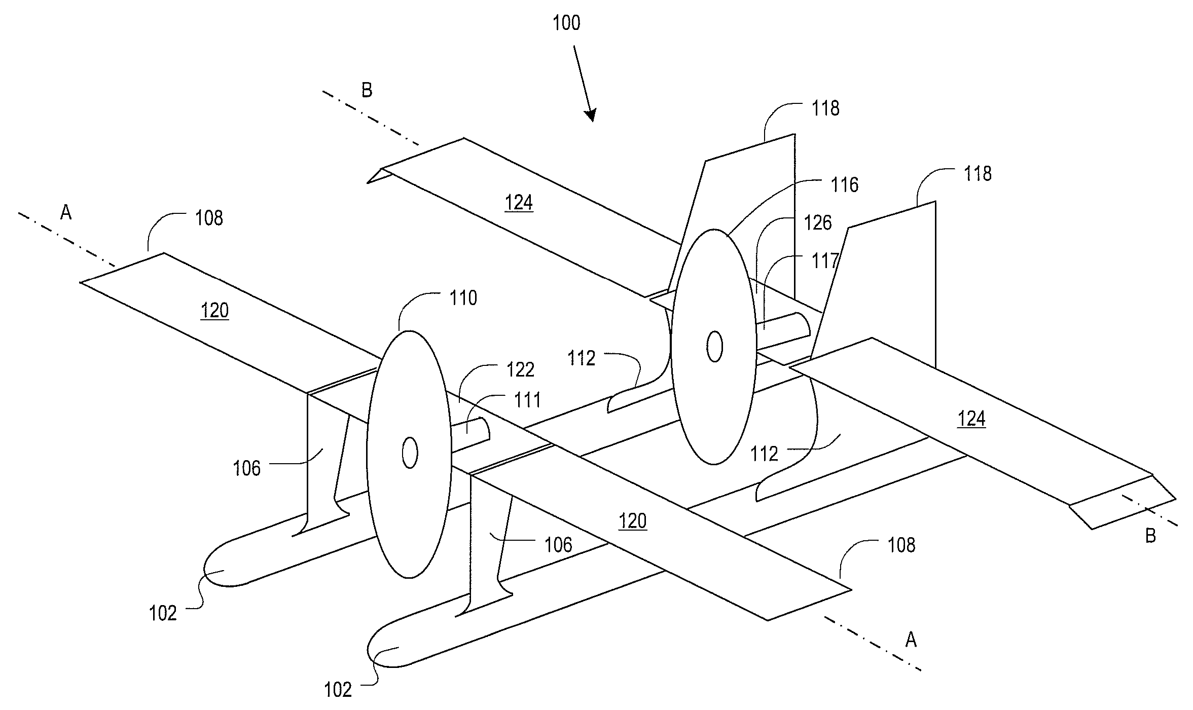
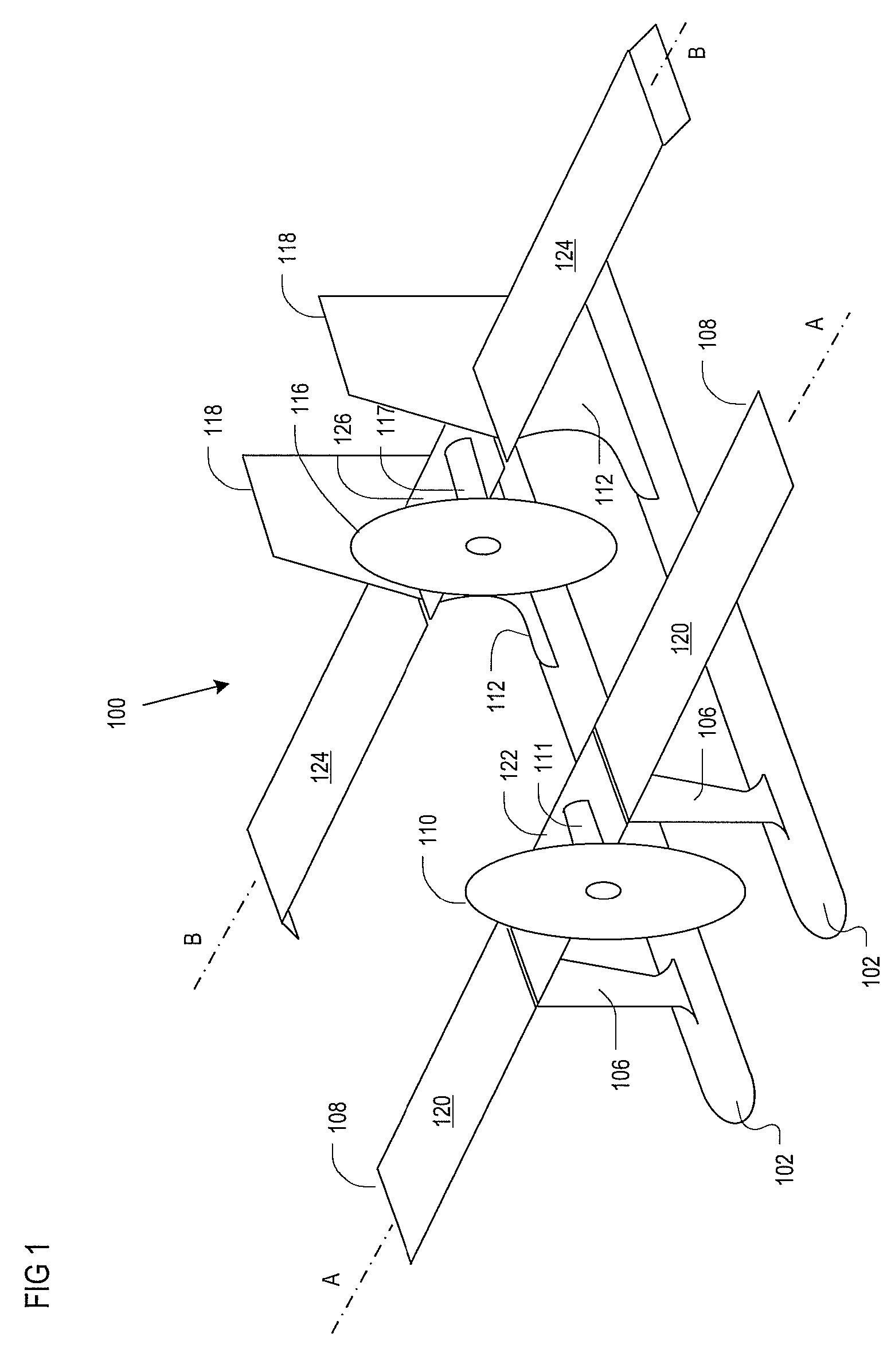
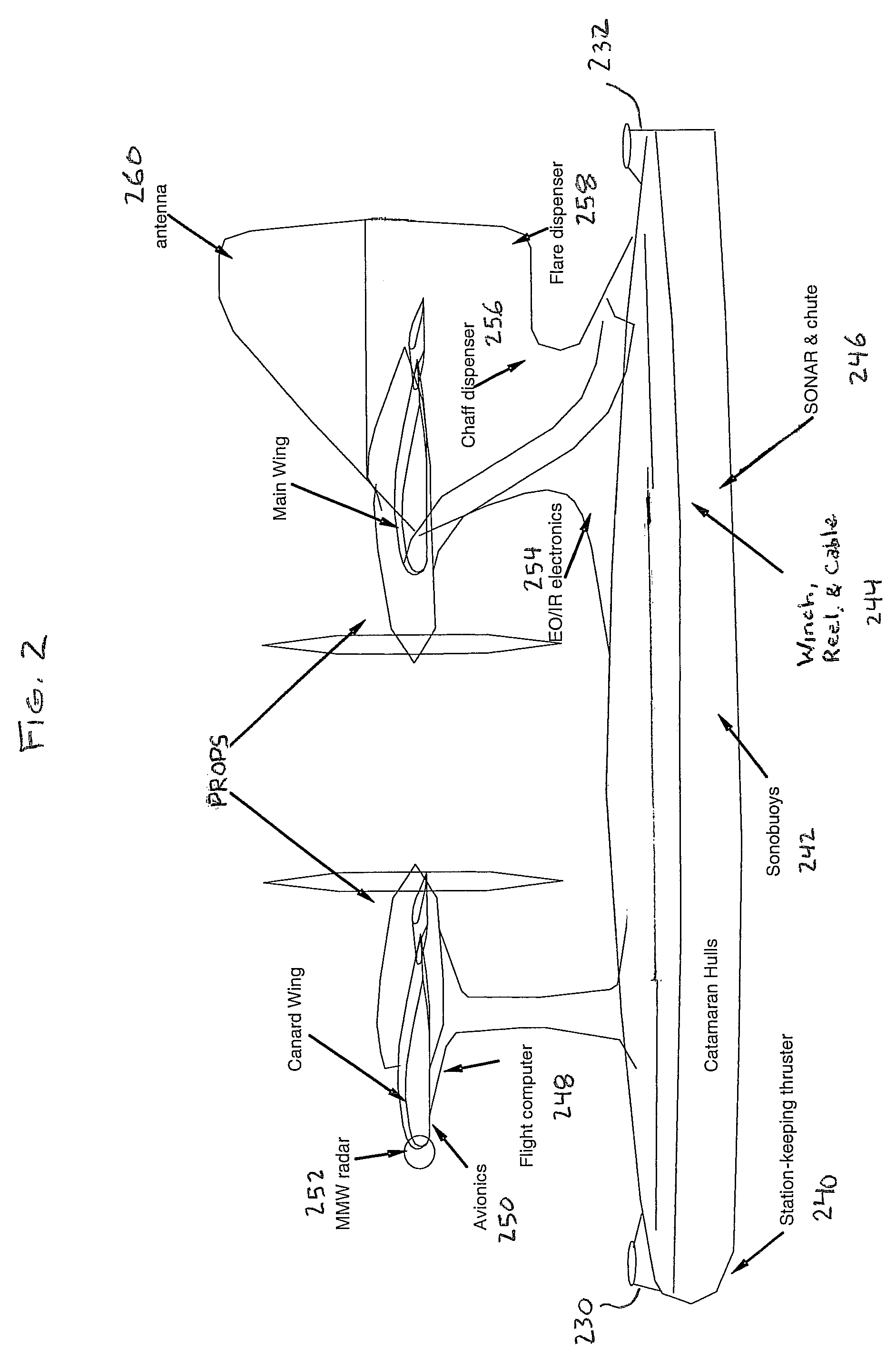
[0042]FIGS. 1-4 depict various views of amphibious aircraft 100 in accordance with the illustrative embodiment of the invention. In particular, FIG. 1 depicts a perspective view, FIG. 2 depicts a side view, FIG. 3 depicts front view, and FIG. 4 depicts a top view.

[0043]Referring now to FIGS. 1-4, amphibious aircraft 100 comprises hulls 102, canard wing support struts 106, canard wing 108, canard wing prop 110, canard wing engine 111, main wing support struts 112, main wing 114, main wing prop 116, main wing engine 117, and tail 118, interrelated as shown.

[0044]In the illustrative embodiment, hulls 102 are semi-submersible, wave-piercing, catamaran “amas.” Referring to FIGS. 5A (side view) and 5B (cross section thru s-s), hulls 102 have ledges or “strakes”576 that provide lifting / planing regions below the waterline.

[0045]In the embodiment that is depicted in FIGS. 2 and 4, hydrofoil “akas”230 and 232 depend from respective fore and aft regions of the top of each hull 102. In an alter...


PUM


Abstract

A multi-wing, multi-engine, multi-hull amphibious aircraft is disclosed. In the illustrative embodiment, the aircraft has an open frame structure without a fuselage.

Description

CROSS REFERENCE TO RELATED APPLICATIONS[0001]This case claims priority of U.S. Provisional Patent Application 60 / 803905, filed on Jun. 5, 2006 and incorporated by reference herein.FIELD OF THE INVENTION[0002]The present invention relates to seaplanes.BACKGROUND OF THE INVENTION[0003]Water take-off and landing of amphibious aircraft depends on the planing performance of support floats (for a float plane) or the main fuselage (for a flying boat).[0004]By definition, planing situates the aircraft atop the sea-way. In this position, the aircraft is subject to the motions of either following atop or “skipping” over the undulating wave surface. This often results in an unstable surface dynamic response, such as “porpoising” motion and even premature ballistic launch off of wave crests. These behaviors can result in near-surface stalls and crashes.[0005]As a consequence, active pilot control and a calm sea-surface environment is required for water take-off and landing. And even with pilot ...

Claims


Application Information

Patent Timeline
Patent Type & Authority Patents(United States)
IPC IPC(8): B64C3/00B64C25/54B64C5/16B64C3/38
CPCB64C3/385B64C29/0033B64C35/00B64C39/04B64C39/08
Inventor SAID, BRIAN R.
Owner LOCKHEED MARTIN CORP
Why Eureka
Try Eureka