Systems and methods for the separation of propylene and propane

a technology of propylene and propane, applied in the field of olefins, can solve the problems of increasing non-ideality of the stream, temperature decrease on separation, and temperature change, and achieve the effect of simplifying the design and operation of the system

Active Publication Date: 2011-01-25
LAIR LIQUIDE SA POUR LETUDE & LEXPLOITATION DES PROCEDES GEORGES CLAUDE
View PDF25 Cites 5 Cited by
  • Summary
  • Abstract
  • Description
  • Claims
  • Application Information

AI Technical Summary

Benefits of technology

The current systems and methods allow membrane-based separation of propylene and propane, without a large change in temperature within or at a surface the membrane separator, thereby allowing a permeate stream and residue stream to be withdrawn at or about the temperature of the feed stream. The near isothermal operation greatly simplifies design, and operation of the system.

Problems solved by technology

Membrane based separation of nonideal organic gases leads to a temperature decrease on separation.
The temperature change increases with increasing non-ideality of the stream.

Method used


Image

  • Systems and methods for the separation of propylene and propane
  • Systems and methods for the separation of propylene and propane
  • Systems and methods for the separation of propylene and propane

Examples


example 1

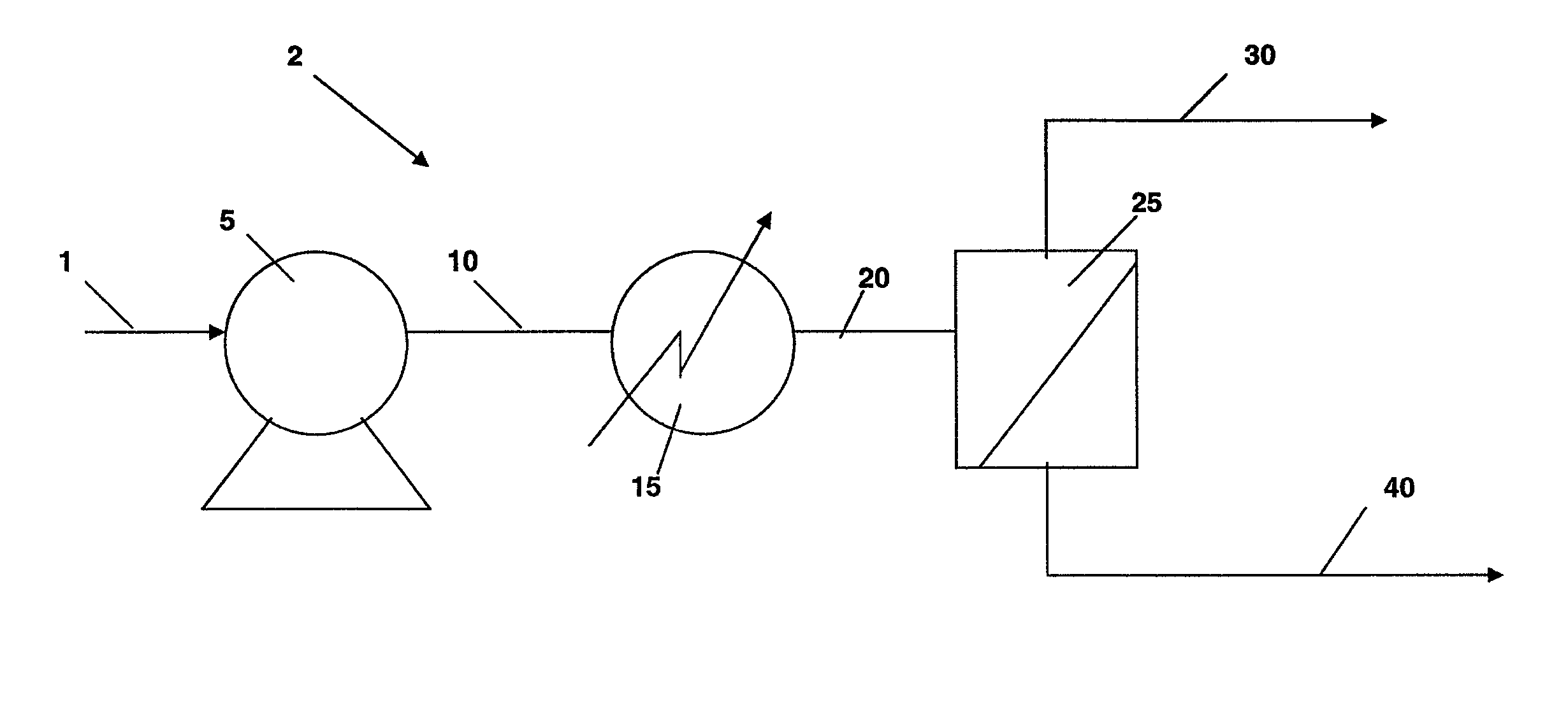
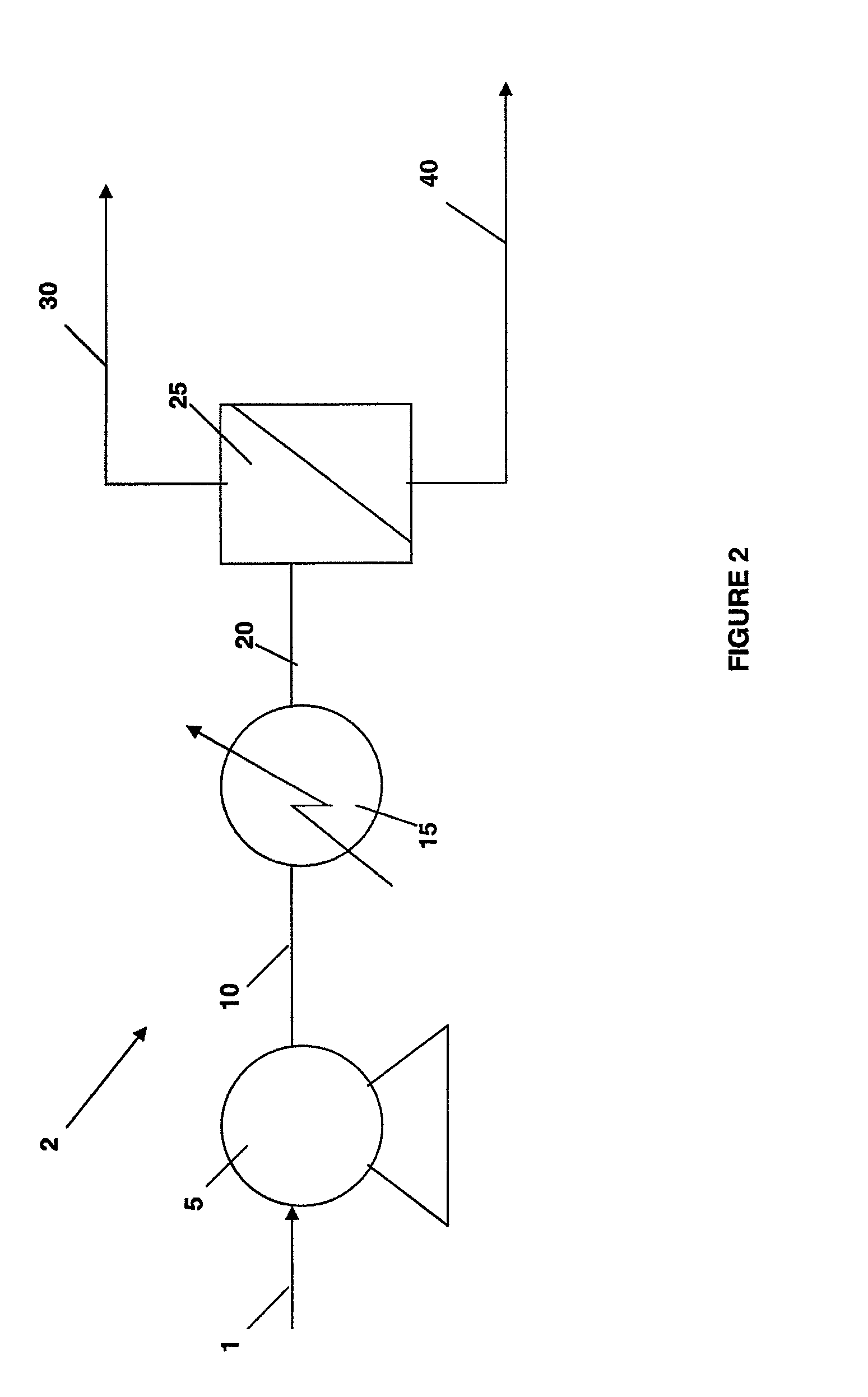
A simulation was performed based upon the system illustrated in FIG. 2. The intent of this system is the recovery of higher purity propylene. The system incorporates a membrane (25) with a propylene to propane selectivity of 11.3 MMscfd. Now referring to FIG. 2, an example of a system of the present invention for the separation of propylene and propane is disclosed. A feed of 3 MMscfd at 200 psia and 30 C is introduced to System 2. Pump 5 pressurizes the stream 500 psia. Evaporator (15) vaporizes the feed reaching an ultimate temperature of 90° C. Membrane (25) with an inherent propylene to propane selectivity of 11 is used to separate the feed into a propylene enriched product (40) and a propane enriched product (30). The propylene product is recovered at 93% propylene purity at 40 psia. Propylene recovery is 70%. The propane purity is 57% and propane recovery is 88%. The pump for this system requires 44 kw and the evaporator (heat exchanger) requires 662 kW. Table 1 lists the vari...

example 2

A simulation was also performed based upon the system illustrated in FIG. 3. The system is capable of high recovery of increased purity propylene and high recovery of increased purity propane. A feed of 3 MMscfd at 200 psia and 30 C is introduced to the system outline in FIG. 2. Pump (315) pressurizes the stream 500 psia. Evaporator (heat exchanger) (325) vaporizes the feed reaching an ultimate temperature of 90° C. Membrane (335) separates the feed into a propylene enriched product at 40 psia (390). The propylene product is compressed to system feed pressure by Compressor (395). The non-permeate stream (340) is reheated to 90 C and further processed by membrane (335) into a 95% propane product (50) and a low pressure propylene-enriched stream. Stream 360 is compressed by compressor (364) and subsequently condensed by condenser (375). The resulting stream is comingled with the feed (301). The combined stream is fed to the membrane system.

A system based on FIG. 3 is capable of produc...

example 3

demonstrates identical performance to Example 2 without the necessity of propylene product compression.

TABLE 4Stream Properties for Example 3Stream #401420430490440441450460T (° C.)3032908282903535P (psia)2005005004049949949930V / L00110.810.51Flow (MMscfd)35.495.492.23.273.270.782.49% propylene7076.2976.2993.163.763.74.982.1% propane3023.7123.716.936.336.395.117.8


PUM

PropertyMeasurementUnit
temperaturesaaaaaaaaaa
pressureaaaaaaaaaa
temperatureaaaaaaaaaa

Abstract

Embodiments of the present invention generally disclose membrane-based systems and methods for the separation of propylene and propane that overcome certain issues associated with prior art devices and take advantage of a temperature drop across the associated separation membrane.

Description

BACKGROUND OF THE INVENTIONOlefins, particularly ethylene and propylene, are important chemical feedstocks. Typically they are found in nature or are produced as primary products or byproducts in mixtures that contain saturated hydrocarbons and other components. Before the raw olefins can be used, they usually must be purified from these mixtures. Numerous difficulties have been experienced in this type of separation. Due to their similar relative volatilities, energy-intensive, capital-intensive, multi-trayed distillation columns typically have been used for the purification of light olefins.An example of a prior art distillation column for the separation of propylene and propane is illustrated in FIG. 1. In an exemplary method of operation, a raw feedstock of Refinery Grade Propylene (RGP) comprising 70% propylene and 30% propane is introduced to distillation column 205 along feed pipe or pipes 200. Distillation column 205 generally comprises multiple trays, or levels. In an embod...

Claims


Application Information

Patent Timeline
Patent Type & Authority Patents(United States)
IPC IPC(8): C07C7/144
CPCB01D53/226B01D61/362C07C7/144C07C9/08C07C11/06B01D2257/7022B01D2311/10B01D2317/022
Inventor SANDERS, JR., EDGAR S.NOEL, FREDERIC P. C. M.
Owner LAIR LIQUIDE SA POUR LETUDE & LEXPLOITATION DES PROCEDES GEORGES CLAUDE
Why Eureka
Try Eureka