Automatic battery reconnection

a battery reconnection and automatic technology, applied in the direction of electric vehicles, emergency power supply arrangements, transportation and packaging, etc., can solve the problems prone to human error in manual closing multiple battery switches after power loss, and prone to errors. , to achieve the effect of reducing the run time of the ups system following a power outage, reducing the damage to the battery pack after a deep discharge, and reducing the error in reconnecting

Active Publication Date: 2011-02-01
SCHNEIDER ELECTRIC IT CORP
View PDF13 Cites 0 Cited by
  • Summary
  • Abstract
  • Description
  • Claims
  • Application Information

AI Technical Summary

Benefits of technology

[0017]Embodiments of the invention may provide one or more of the following capabilities. Battery damage in UPS systems due to deep discharge can be reduced. Run time of UPS systems following a power outage can be improved. A battery pack of a UPS system can be disconnected from a UPS system's power circuitry before full discharge of the battery pack during power outage. Disconnected battery packs of UPS systems can be automatically reconnected to power circuitry of the UPS systems after a power outage in response to power being restored to the UPS systems. Errors in reconnecting battery packs after a power failure can be reduced. Battery packs can be reconnected at correct times after a UPS DC bus has been charged to a suitable level subsequent to power restoration. Damage to UPS systems (e.g., Delta Conversion of UPS) can be inhibited or prevented.

Problems solved by technology

Uninterruptible power supply (UPS) systems typically have backup power supplied by batteries.
Manually closing multiple battery switches after a loss of power is prone to human error.
This process is tedious and prone to error.
A switch that is not properly reset can substantially reduce the run time of the UPS system 10 and result in damage, e.g., due to deep discharge of battery packs 16.

Method used


Image

  • Automatic battery reconnection
  • Automatic battery reconnection
  • Automatic battery reconnection

Examples


Embodiment Construction

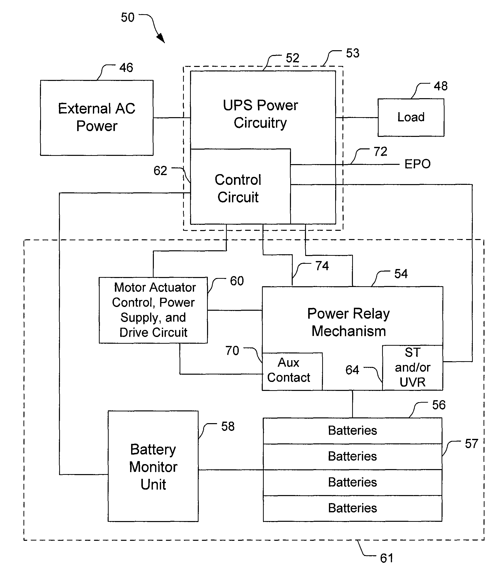
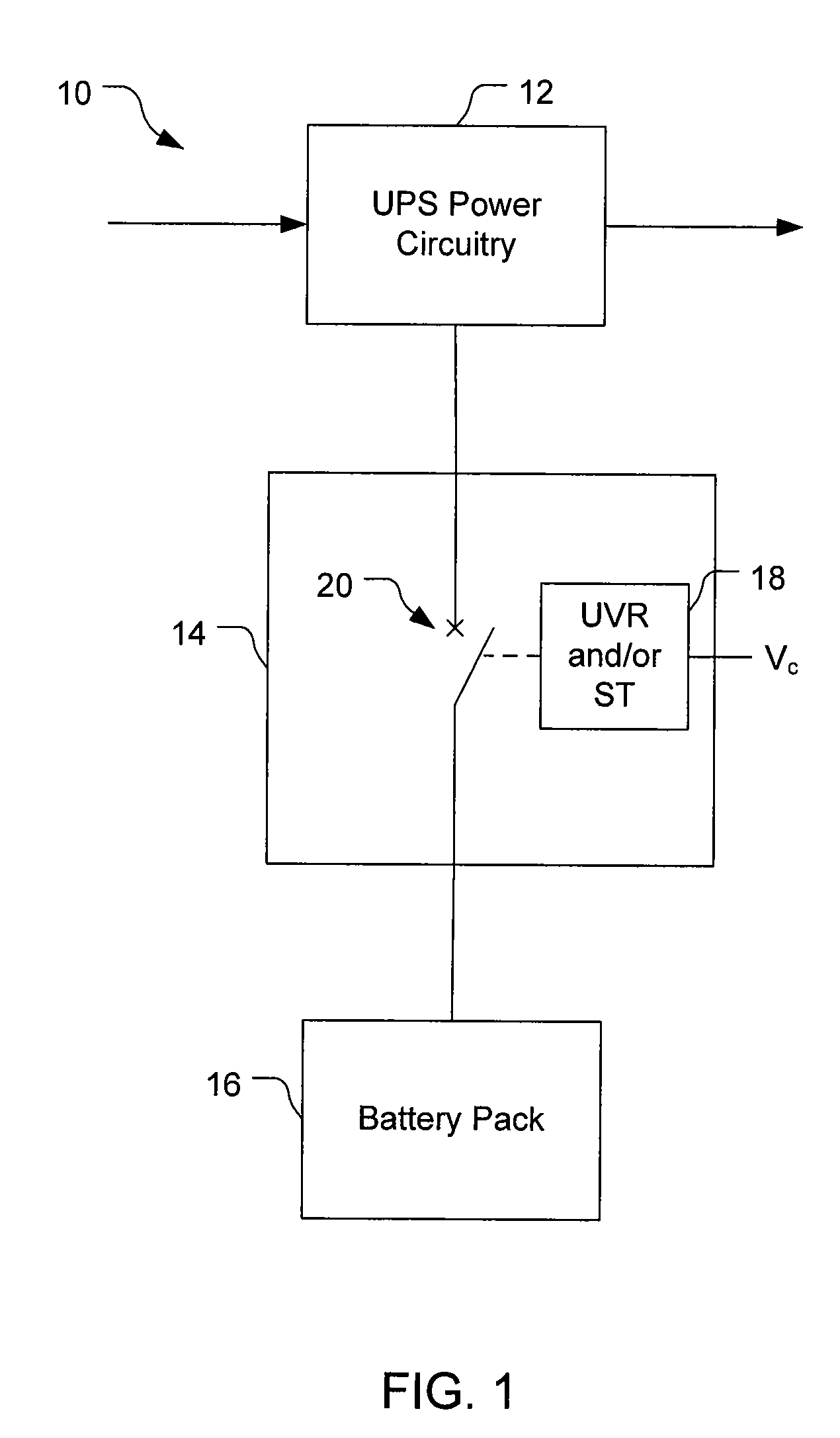
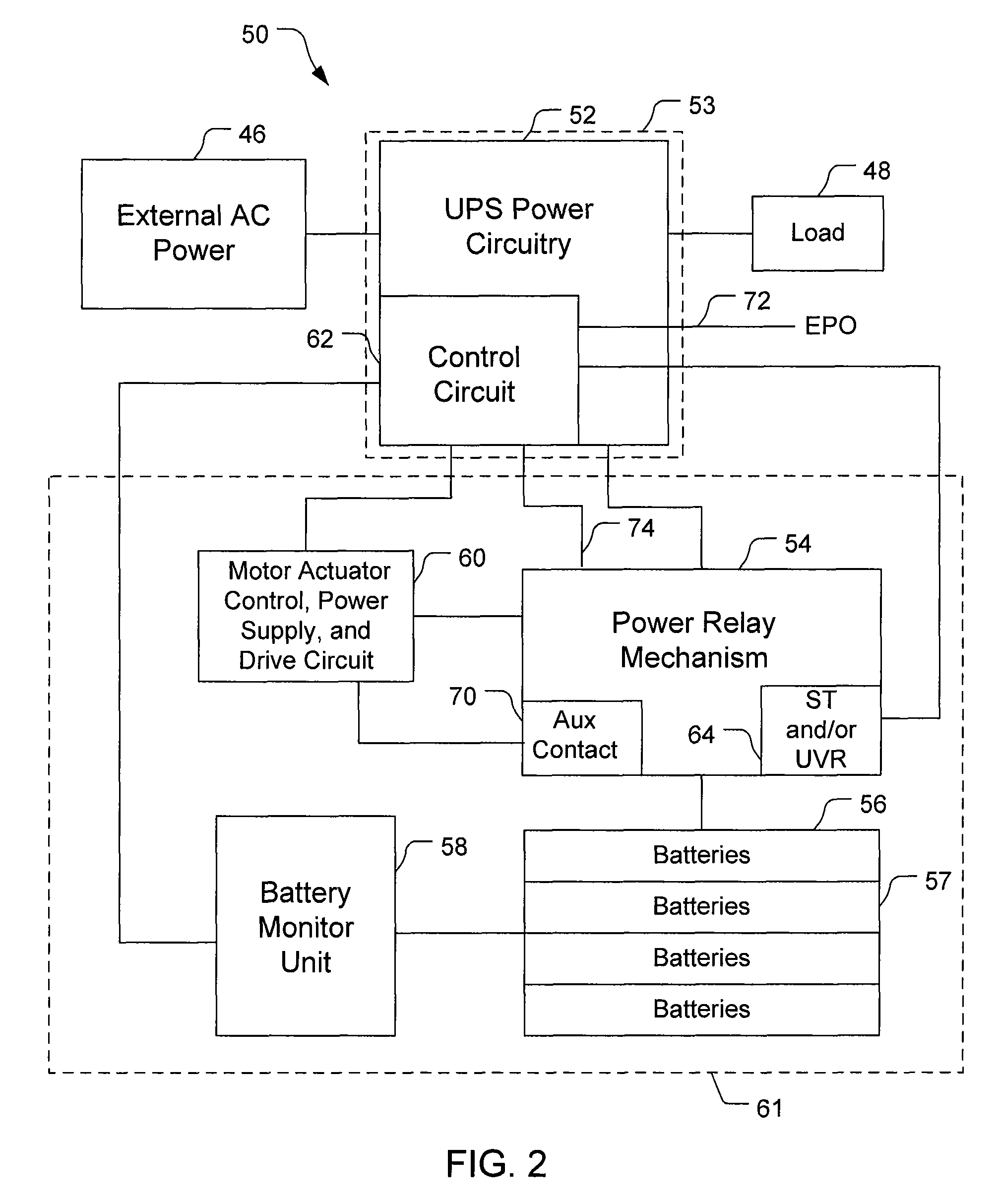
[0023]Embodiments of the invention provide techniques for reconnecting batteries to power circuitry in UPS systems. A motor actuator is provided in a power relay mechanism of a UPS system that can close a circuit breaker or switch (hereafter “switch”) without human involvement. The motor actuator can respond to power being available to a UPS system to close a switch that has been opened in response to a loss of supply power, a reduction in supply power, a voltage from a battery pack below a threshold, or other reason. Intelligence within the UPS system controls the motor actuator to close the switches as appropriate. Other embodiments are within the scope of the invention.

[0024]Referring to FIG. 2, a UPS system 50 for use with an external AC power supply 46 and a load 48 includes UPS power circuitry 52, a power relay mechanism 54, a battery pack 56, a battery monitor unit 58, and a motor unit 60. The motor unit 60 includes a motor actuator control, a power supply, and a drive circui...


PUM


Abstract

An uninterruptible power supply system includes power converter circuitry configured to convert AC input power to a first DC power and a second DC power to the first DC power, a battery pack configured to provide the second DC power, a power relay mechanism coupled to the power converter circuitry and to the battery pack that selectively moves between an open position and a closed position, the power relay mechanism coupling the battery pack to the power converter circuitry when in the closed position and isolating the battery pack from the power converter circuitry when in the open position, and control circuitry configured to provide a control signal, where the power relay mechanism includes a motor actuator coupled to the control circuitry, the motor actuator being responsive to the control signal to change the power relay mechanism from the open position to the closed position.

Description

BACKGROUND[0001]Uninterruptible power supply (UPS) systems typically have backup power supplied by batteries. For example, referring to FIG. 1, a UPS system 10 includes power circuitry 12, a power relay mechanism 14, and a battery pack 16. The battery pack 16 includes multiple batteries connected in series to supply DC voltage to the power circuitry 12. The mechanism 14 connects the circuitry 12 to the battery pack 16 to supply power from the battery pack 16 to the circuitry 12, to supply from the circuitry 12 to the battery pack 16, and can disconnect the circuitry 12 from the battery pack 16 to inhibit energy transfer between the circuitry 12 and the battery pack 16.[0002]The mechanism 14 acts as a breaker or switch to act as a disconnecting means, e.g., as required by safety codes because a source of power (here, the battery pack 16) must be disconnected from the power circuitry 12 during an emergency, or for non-code purposes such as maintenance of the UPS system 10. The mechani...

Claims


Application Information

Patent Timeline
Patent Type & Authority Patents(United States)
IPC IPC(8): H02J9/00
CPCH02J9/06H02J9/062H02J9/061
Inventor ZIEGLER, WILLIAM E.KULKARNI, ASHOK B.
Owner SCHNEIDER ELECTRIC IT CORP
Why Eureka
Try Eureka