
Beacon signal generating apparatus in satellite communication system and phase synchronizing apparatus using the same

a satellite communication system and signal generating technology, applied in the direction of synchronisation arrangement, wireless commuication services, broadcast with distribution, etc., can solve the problems of data transmission error rate, complicated hardware and software structure and algorithm, etc., to achieve simple hardware and software structure, the effect of removing the data transmission error ra

Inactive Publication Date: 2011-02-01
ELECTRONICS & TELECOMM RES INST
View PDF10 Cites 3 Cited by
  • Summary
  • Abstract
  • Description
  • Claims
  • Application Information

AI Technical Summary

Benefits of technology

The present invention provides an apparatus for generating a beacon signal in a satellite and a phase synchronizing apparatus for a satellite communication system. The apparatus includes a frequency oscillating means for creating a TSO frequency, a beacon signal generating means for synchronizing the TSO frequency with a beacon signal frequency, and a transmitting means for transmitting the synchronized beacon signal. The technical effect of the invention is to establish a precise synchronization between the OBS and the earth stations in a SS-TDMA satellite communication system, preventing data loss due to phase differences and ensuring efficient use of limited satellite output.

Problems solved by technology

In addition, signal loss is taken place if an operation clock of the OBS 10 embedded in the satellite is not precisely synchronized with that of the earth stations 20 to 40.
However, the existing method has a drawback in that its hardware and software structure and algorithm are complicated to detect the phase error of VCXO in the satellite by the earth station and calculate the correction value.
This makes the hardware and software structure and algorithm complicated.

Method used


Image

  • Beacon signal generating apparatus in satellite communication system and phase synchronizing apparatus using the same
  • Beacon signal generating apparatus in satellite communication system and phase synchronizing apparatus using the same
  • Beacon signal generating apparatus in satellite communication system and phase synchronizing apparatus using the same

Examples


Embodiment Construction

[0023]The above-mentioned objectives, features, and advantages will be more apparent by the following detailed description associated with the accompanying drawings; and based on this, the invention will be readily conceived by those skilled in the art to which the invention pertains. Further, in the following description, well-known arts will not be described in detail if it seems that they could obscure the invention in unnecessary detail. Hereinafter, a preferred embodiment of the present invention will be set forth in detail with reference to the accompanying drawings.

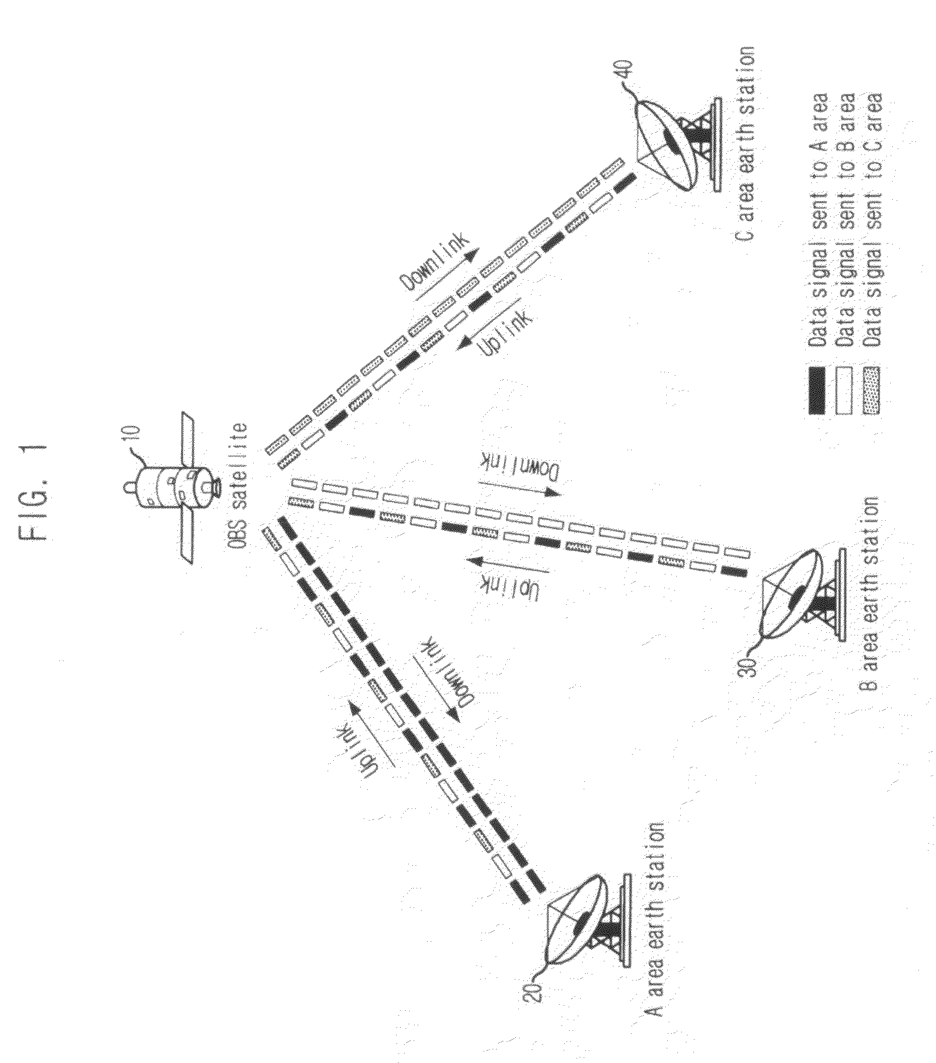
[0024]FIG. 1 is a diagram illustrating a structure of a satellite communication system to which the present invention is applied, especially of SS-TDMA satellite communication system that does multi-beam communication.

[0025]As set forth above, for satellite communication of SS-TDMA scheme, it is required that a clock synchronization between an OBS 10 embedded in a satellite and earth stations 20 to 40 be establishe...


PUM


Abstract

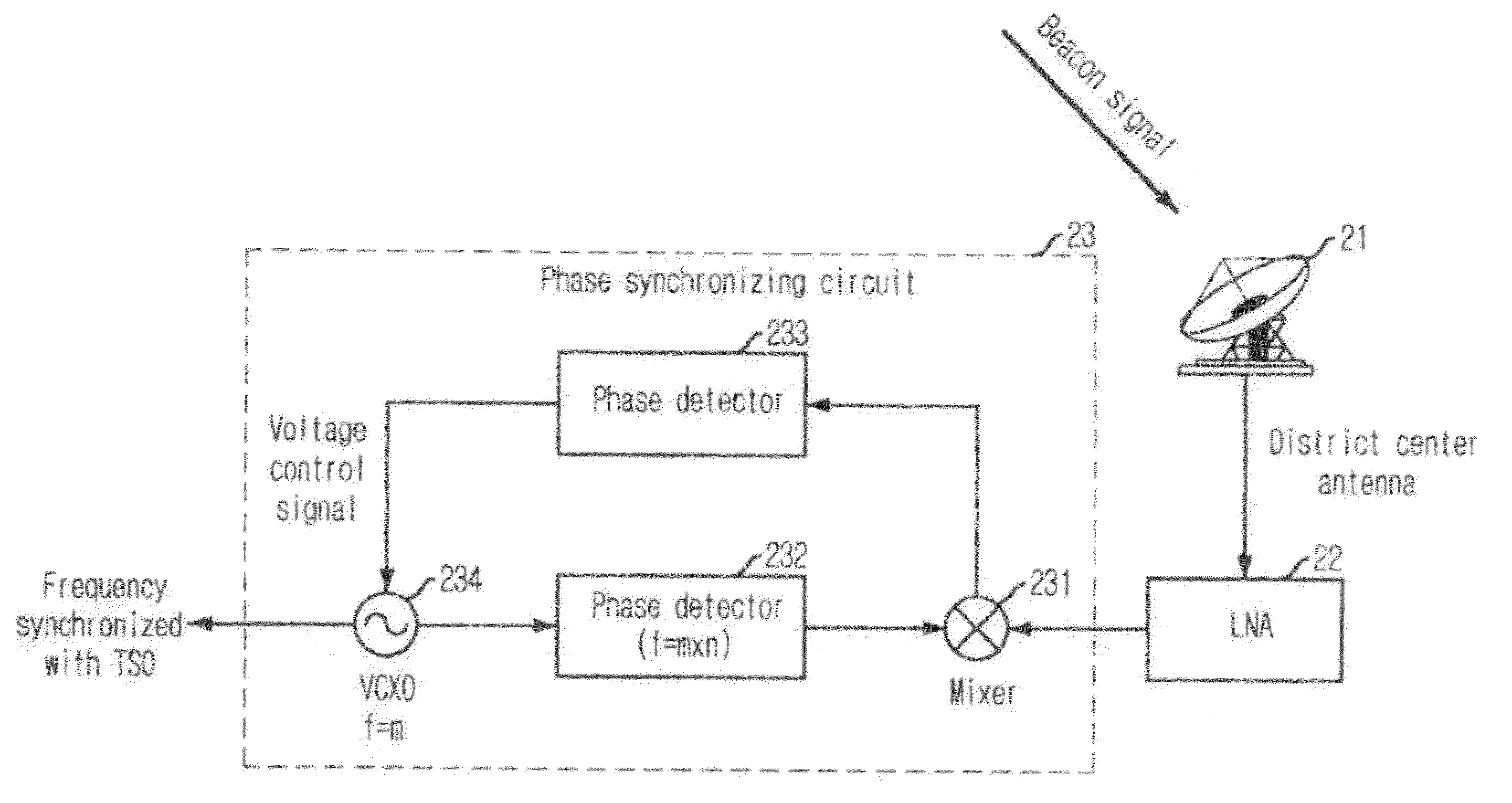
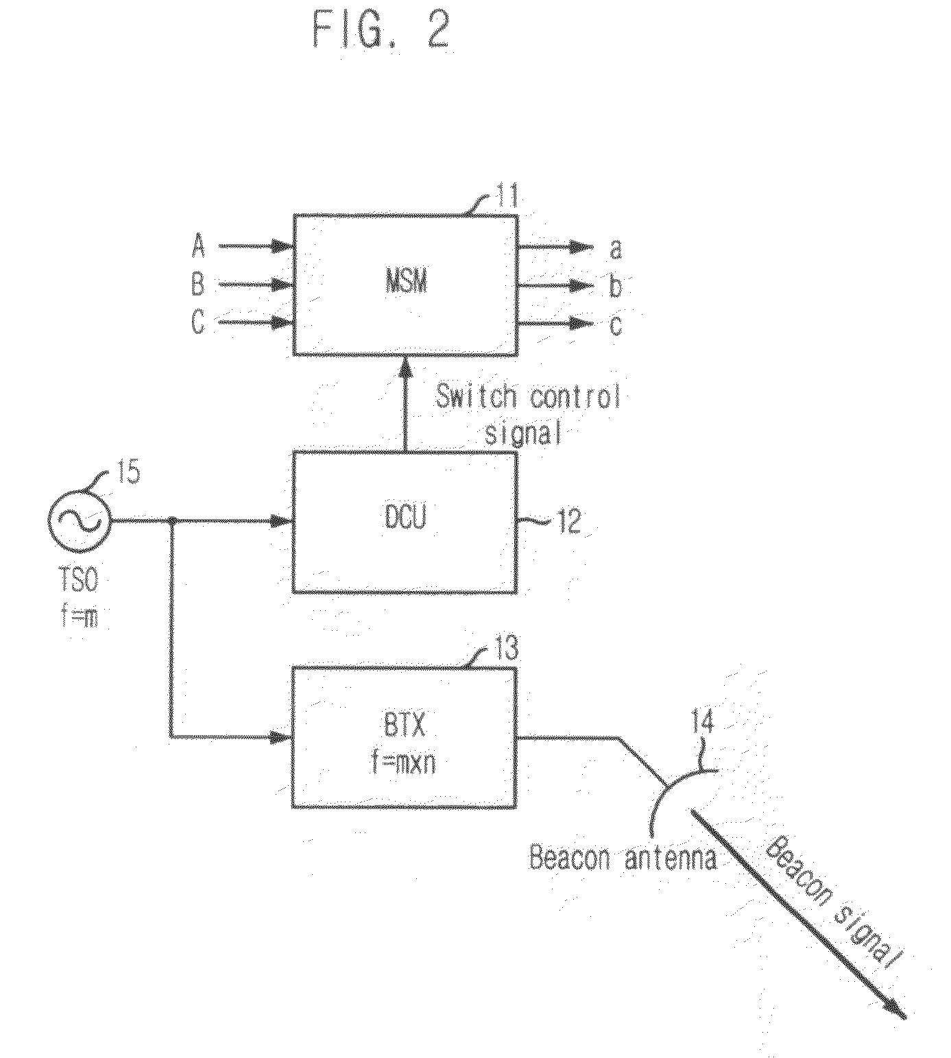
Provided are a beacon signal generating apparatus and a phase synchronizing apparatus using the same for establishing a phase synchronization while tracking a phase variation of a Timing Source Oscillator (TSO) of a satellite using a simpler scheme at an earth station, in making a phase synchronization between a clock signal of an On board Switch (OBS) embedded in the satellite and that of the earth station in a Satellite Switched Time Division Multiple Access (SS-TDMA) satellite communication system. The inventive beacon signal generating apparatus embedded in a satellite comprises a frequency oscillator for creating a TSO frequency, a beacon signal generator for multiplying the TSO frequency to be matched with a beacon signal frequency to generate a beacon signal synchronized with the TSO frequency, and a transmitter for transmitting the beacon signal to each of earth stations to recovery a frequency synchronized with the TSO frequency.

Description

TECHNICAL FIELD[0001]The present invention relates to a beacon signal generating apparatus for clock synchronization between an On Board Switch (OBS) and an earth station in a satellite communication system and a phase synchronizing apparatus using the same; and more particularly, to a beacon signal generating apparatus and a phase synchronizing apparatus using the same for preventing data loss by phase difference of clock by maintaining a synchronization between a clock signal of an OBS embedded in a satellite and that of an earth station in a Satellite Switched Time Division Multiple Access (SS-TDMA) satellite communication system that does multi-beam communication.BACKGROUND ART[0002]There is provided a common method for establishing a clock synchronization between an OBS embedded in a satellite to conduct a multi-beam switching function and a satellite communication earth station referring to FIG. 1.[0003]Differently from an existing communications satellite that simply converts...

Claims


Application Information

Patent Timeline
Patent Type & Authority Patents(United States)
IPC IPC(8): H04B7/19
CPCH04B7/18589H04B7/2125H04B7/155H04W56/00
Inventor JO, JIN-HOLEE, SEONG-PAL
Owner ELECTRONICS & TELECOMM RES INST
Learn More