Oil bypass device, and engine fitted with such a device

a bypass device and oil technology, applied in the direction of cartridge filter, cleaning of hollow articles, corrosion prevention, etc., can solve the problems of oil pressure, oil pressure, and progressive increase of the head loss of the filter, so as to avoid the risks of failure, and improve the reliability of operation

Active Publication Date: 2011-02-08
BONTAZ CENT
View PDF6 Cites 1 Cited by
  • Summary
  • Abstract
  • Description
  • Claims
  • Application Information

AI Technical Summary

Benefits of technology

[0015]An object of the present invention is to design a safety device that assures improved reliability of operation, avoiding the risks of failure of the safety valve in the case of soiling, and avoiding the risks of failure by deformation of the return leaf springs.
[0022]The valve structure with a tubular piston, which moves transversely relative to the longitudinal axis of the orifice, is much less sensitive to any blockage caused by accumulation of particles carried by the fluid to be filtered. This prevents sealing defects.
[0023]Moreover, the area of the piston on which the differential fluid pressure generates a driving force in its direction of movement is the only radial facet of the external annular recess, and its area is not modified by the total or partial closing of the valve. This results in a further reduction of any risk of sealing defects.

Problems solved by technology

During operation, because of wear of the various moving parts and the oil, particles are found in suspension in the lubricating and cooling oil, and it is necessary to filter the oil to prevent the propagation of these particles, which can be abrasive, to the moving parts of the engine.
These particles progressively clog the filter in operation, which causes a progressive increase in the head loss in the filter.
The problem also arises when starting under wintry conditions.
The reduction in the oil pressure downstream of the filter risks leading to the destruction of the engine if the lubrication of the moving parts of the engine becomes insufficient or if the cooling of the engine becomes insufficient.
The increase in the head loss tends to increase the pressure upstream of the filter.
This upstream pressure can become prohibitive, with the risk of breaking certain parts such as seals or the filter.
Any such breaking of seals suddenly interrupts the lubrication of the engine and also leads to its virtually immediate destruction.
The operation of changing the filters is left to the assessment and the good intentions of the user, however, and the risk therefore remains of leaving a filter in place for too long and it becoming excessively clogged.
The greatest risk is the excessive increase in pressure in the pipes upstream of the filter, in the case of excessive clogging of the filter.
However, it is clear that the quantity of oil that passes through the filter is then reduced commensurately, which accentuates the phenomenon of reduced lubrication and cooling of the moving parts of the engine, again with the risk of destruction of the engine.
However, there is then the problem that correct operation of the device necessitates always having available a filter provided with a bypass valve.
On changing the filter, if the user fits a filter that is not provided with any such bypass valve, the safety function is then absent, and the risks associated with progressive excessive clogging of the filter are encountered again.
Clearly these known devices do not have the sufficient reliability that might be expected of a safety device.
In particular, because of the particular conditions of use of the valves in the presence of a fluid that is charged with impurities and that must be filtered, risks of failure remain in the case of soiling of the closure part or the orifice, or in the case of the closure part adopting an off-center position as a result of deformation of the return leaf springs: the seal is then no longer provided, an uncontrolled leak occurs, and the filtering becomes insufficient.

Method used


Image

  • Oil bypass device, and engine fitted with such a device
  • Oil bypass device, and engine fitted with such a device
  • Oil bypass device, and engine fitted with such a device

Examples


Embodiment Construction

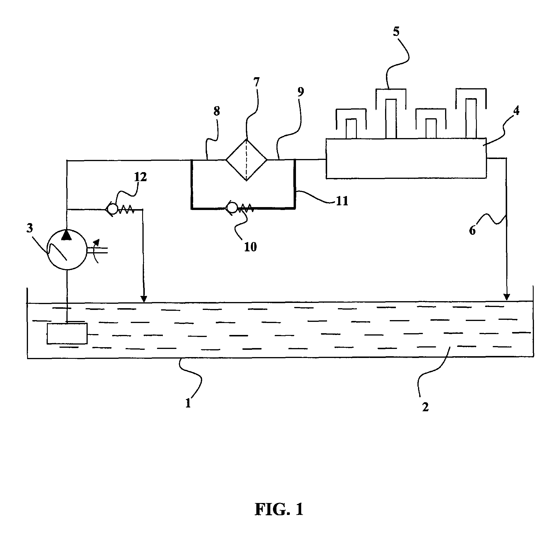
[0041]Consider first FIG. 1, which shows the general structure of an oil distribution circuit for cooling and lubricating moving parts of an engine.

[0042]The engine comprises, in the lower portion, a sump 1 that receives and contains an oil reserve 2. A pump 3 takes oil from the sump 1 and sends it under pressure in a distribution passage to an oil distribution network 4 that directs the oil to the moving parts such as the pistons 5 of the engine and the vital parts such as the crankshaft bearings of the engine. The oil then returns to the sump via a return passage 6.

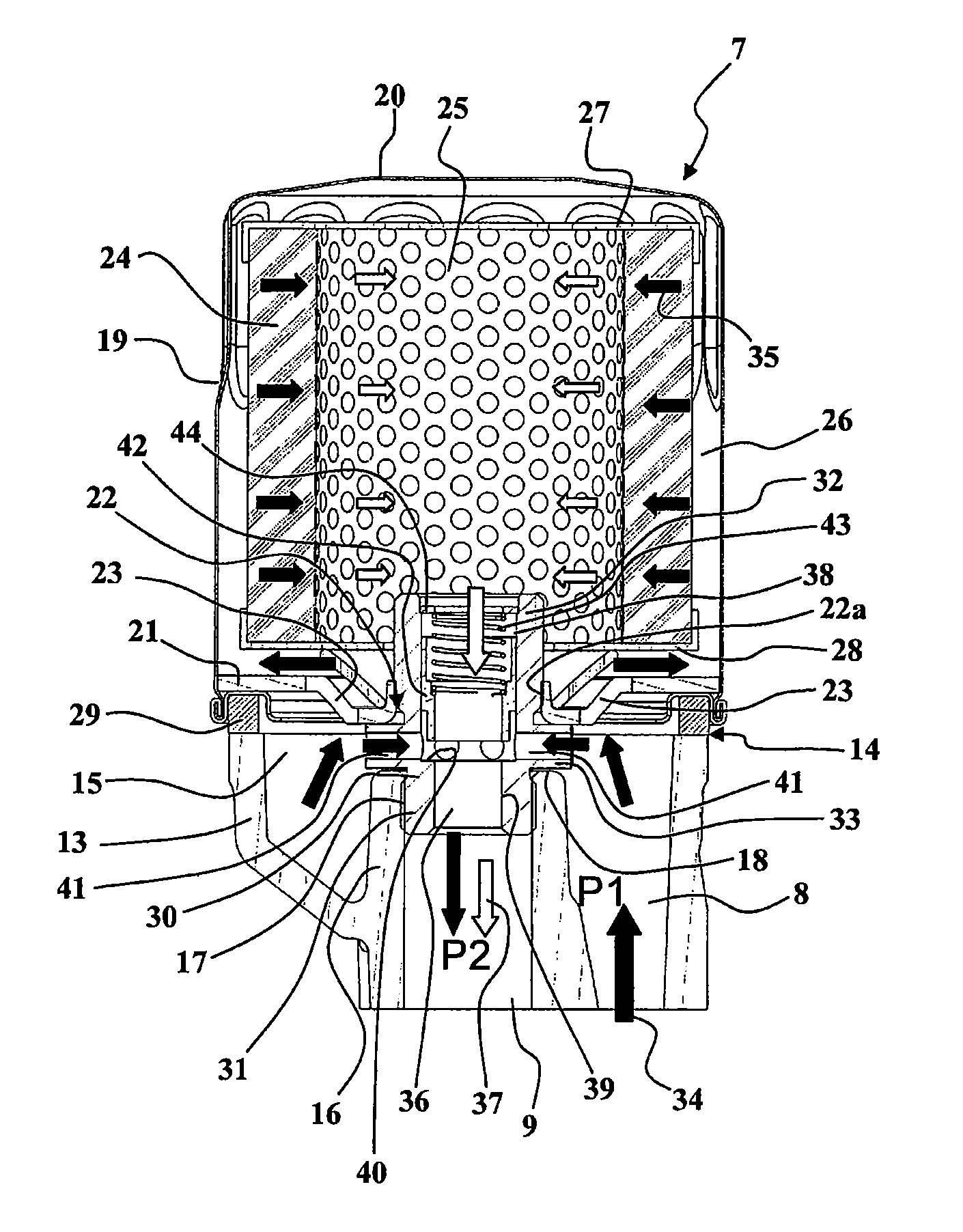
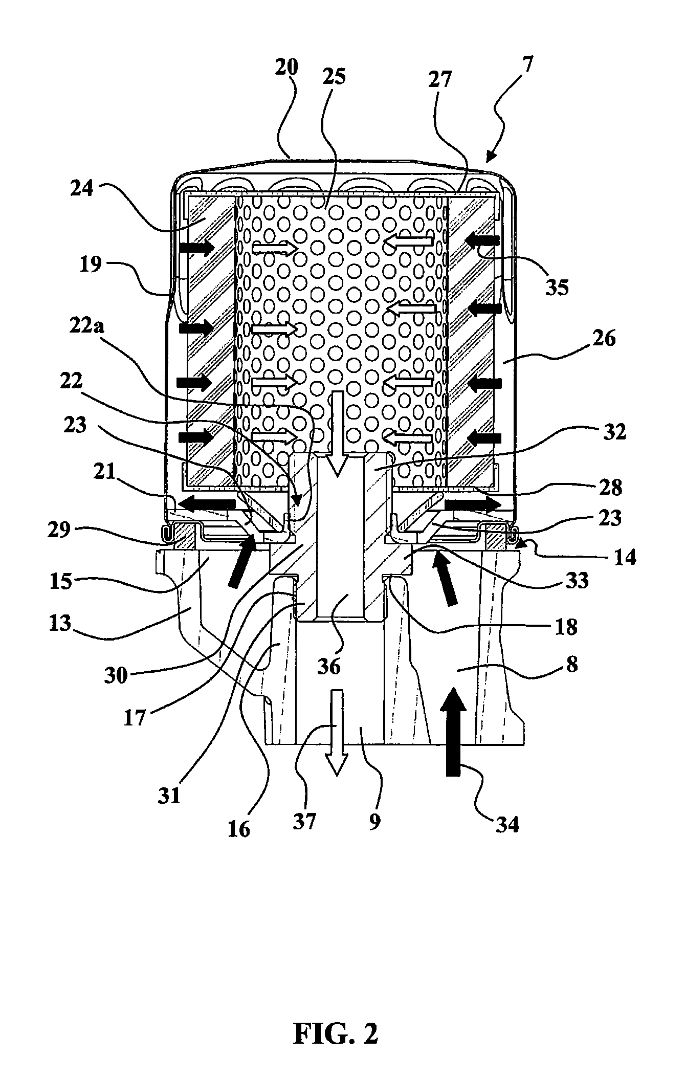
[0043]In the distribution passage, a filter 7 is inserted between the pump 3 and the oil distribution network 4. The filter 7 is interchangeable, and thus is connected in a removable and sealed manner between an inlet passage 8 and an outlet passage 9 of the distribution pipe.

[0044]A bypass valve 10 is connected between the inlet passage 8 and the outlet passage 9 by a bypass passage 11. A relief valve 12 provides selec...


PUM

PropertyMeasurementUnit
differential pressureaaaaaaaaaa
diameteraaaaaaaaaa
pressureaaaaaaaaaa

Abstract

According to the invention, the filter is fixed to the engine block by screwing it to an attached connecting sleeve. The connecting sleeve contains a bypass valve, in the form of a tubular piston sliding in a through-passage and pushed against an intermediate shoulder by a spring. By sliding, the piston opens or closes a radial passage establishing direct communication between the inlet passage and the through-passage of the device. If the filter element of the filter is clogged, the pressure rise in the inlet passage causes the piston to move and the radial passage to open to reduce the pressure rise and ensure a satisfactory flow of oil. This reduces pressure rises upstream of the filter and ensures sufficient lubrication of the engine even in the case of clogging of the filter.

Description

TECHNICAL FIELD OF THE INVENTION[0001]The present invention concerns circuits for distributing oil in heat engines such as internal combustion engines.[0002]Internal combustion engines comprise moving parts such as pistons, crankshafts, etc., which must be fed continuously with lubricating and / or cooling oil.[0003]For this, engines include a pressurized oil supply device, taking oil from a sump in the lower portion of the engine, pressurizing the oil by means of a pump to feed it into a network for distributing oil to the moving parts of the engine, the oil then returning to the sump.[0004]During operation, because of wear of the various moving parts and the oil, particles are found in suspension in the lubricating and cooling oil, and it is necessary to filter the oil to prevent the propagation of these particles, which can be abrasive, to the moving parts of the engine. A filter capable of blocking the particles in suspension is provided for this purpose, in the circuit between th...

Claims


Application Information

Patent Timeline
Patent Type & Authority Patents(United States)
IPC IPC(8): B01D27/10B01D35/14
CPCB01D27/103F01M11/03F01M2001/1092Y10T137/87362
Inventor BONTAZ, CHRISTOPHEBONVALOT, MICHAELPEROTTO, STEPHANE
Owner BONTAZ CENT
Why Eureka
Try Eureka