Apparatus for the uniform distribution of fibers in an air stream

a fiber and air stream technology, applied in the direction of fibre treatment, coating, lap forming devices, etc., can solve the problems of cumbersome apparatus, unimportant tactile and absorbency properties, and complex mechanical devices, and achieve the effect of simple and effective

Active Publication Date: 2011-02-15
BIAX FIBERFILM CORP
View PDF43 Cites 5 Cited by
  • Summary
  • Abstract
  • Description
  • Claims
  • Application Information

AI Technical Summary

Problems solved by technology

All of these apparatus have been cumbersome, highly complex mechanical devices which have had several disadvantages in their operations.
Air forming of wood pulp fibrous webs has been carried out for many years; however, the resulting webs have been used for applications where either little strength is required, such as for absorbent products—i.e., pads—or applications where a certain minimum strength is required but the tactile and absorbency properties are unimportant—i.e., various specialty papers.
However, Clark and his associates encountered serious problems with these types of forming systems as a result of disintegration of the fibers by mechanical co-action of the rotor blades with the chamber wall and / or the screen mounted therein which caused fibers to be “rolled and formed into balls or rice which resist separation”—a phenomenon more commonly referred to today as “pilling”.
Clark encountered problems producing a web having a uniform cross-direction profile, because the fiber input and fiber path through the rotary former was not devoid of cross flow forces.
Even though further evolution of this process has led to the use of air to assist the doffing of the fibers off the main cylinder and in forming a web, these processes do not lend themselves well to short cellulosic fibers which are typically in the 2 to 3 mm in length.
The disadvantage of this process was the fact that it was limited to the amount of short cellulose fibers that it could handle.
So if they are not adequate there are no means of correcting of adjusting for them during the formation process.
It is quite obvious from the construction of the entire forming head, which applies the “fiber sifting” technique for obtaining fiber uniformity in the traverse direction, that the inlet funnel that is used lacks the design features to operate solely as the forming head.
The type of fiber sifting equipment described in the Kroyer patents suffers from poor productivity especially when making light weight webs.
Thus, a large percentage of the sifting screen area is poorly utilized and the system productivity is low.
This process had several disadvantages, as the air stream employed for web forming could not be properly psychometrically conditioned, impacting the quality of the web due to static clumping as a result of very dry fluff fibers.
However, this system requires preparation of pre-formed rolls of fibers having high cross-directional uniformity and is not suitable for use with bulk or baled fibrous materials, such that, to date, the system has not found a commercial application.
It is handicapped by the fact that it is a combination defibrator and air former which does neither function well.
They also would suffer severely from great width capability limitations.
These techniques would not work at all in distributing the fibers to the forming section with short cellulose fibers which are the primary component of our fiber stream as the turbulence in the air stream would not provide the uniform distribution required in the cross direction.
Even though these types of devices have been used successfully in the textile industry with staple fibers, the speed of fiber distribution inside the spreading device will not be able to keep up with the throughput requirements of the forming device for high speed short fiber airlaid non-woven forming processes.

Method used


Image

  • Apparatus for the uniform distribution of fibers in an air stream
  • Apparatus for the uniform distribution of fibers in an air stream
  • Apparatus for the uniform distribution of fibers in an air stream

Examples


Embodiment Construction

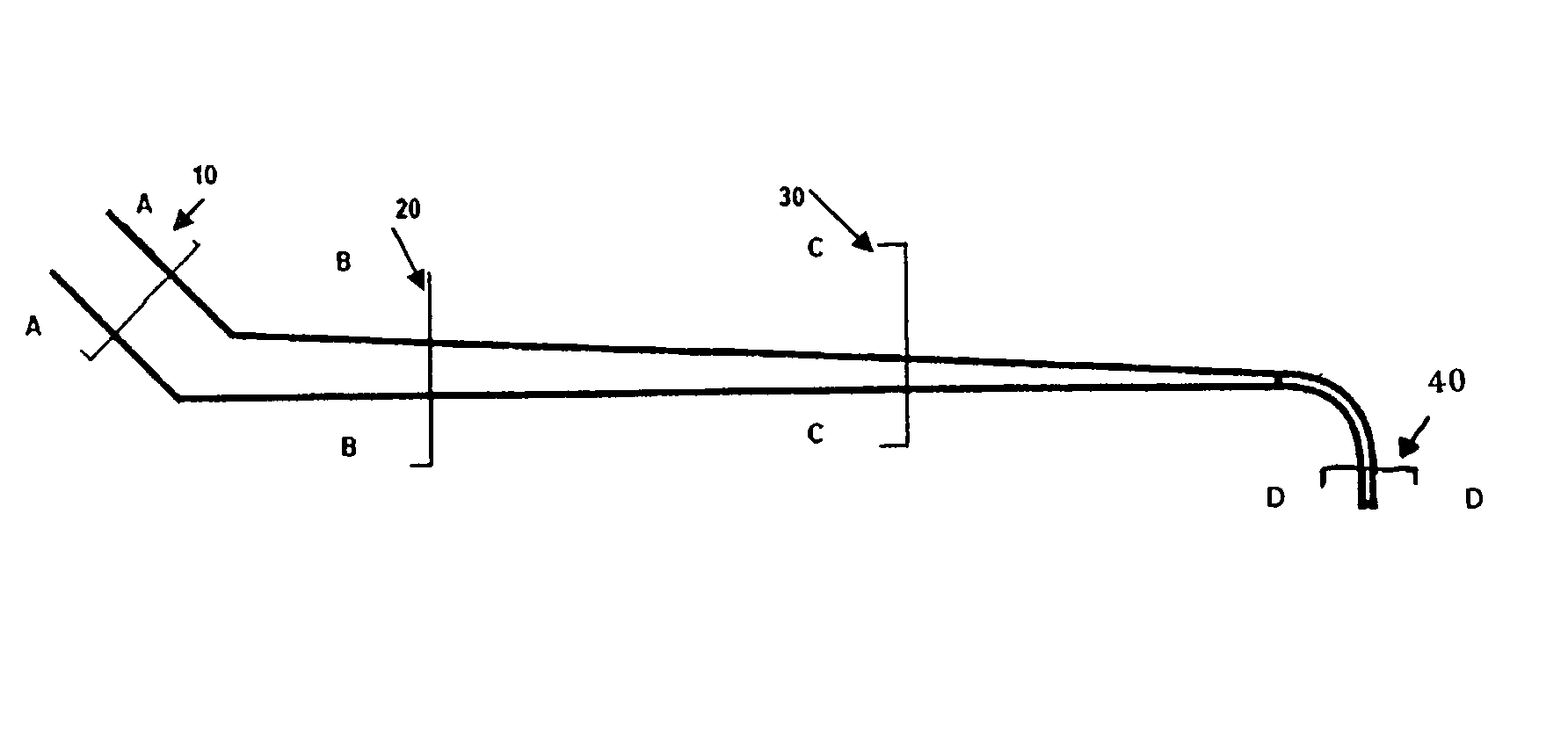
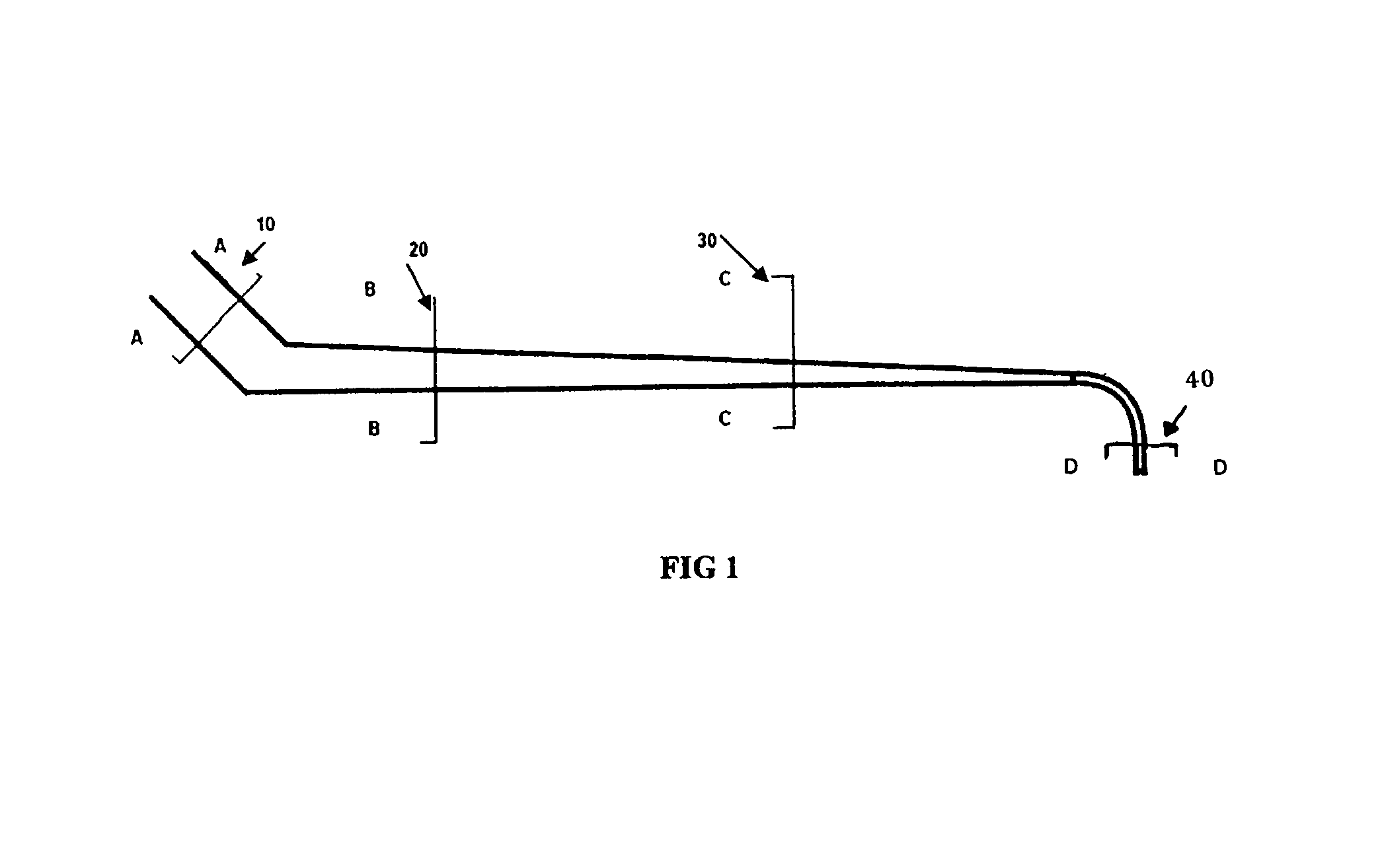
[0032]This invention simplifies what has been attempted before in a very elegant aerodynamic execution of a device which not only distributes the fibers uniformly in the cross machine direction, but also allows them to be formed into a web when injected onto a forming zone and can be expanded laterally to accommodate any width of the forming zone.

[0033]The key aerodynamic parameters for conveying solid particles or fibers in an air stream are well known and published in the art. The difficulty has been in developing a forming head that can maintain these conditions continuously and distribute fibers onto a forming zone at the uniformity levels and the forming zone widths desired.

[0034]A forming zone in most air laid machines is a foraminous screen supported over a vacuum box to consolidate the individual fibers into a web after the air is removed. Other types of forming zones are rotary vacuum drums or condensers into which the air is blown into and the fibers are condensed into a w...


PUM

PropertyMeasurementUnit
angleaaaaaaaaaa
angleaaaaaaaaaa
angleaaaaaaaaaa

Abstract

An apparatus for the manufacture of an air laid web in which individual cellulose fibers or textile fibers or their blends can be conveyed and distributed by air uniformly to any desired width onto a forming zone composed of either a foraminous screen or a fibrous polymer matrix on top of a consolidating vacuum box.

Description

CROSS REFERENCE TO RELATED APPLICATION(S)[0001]This is a continuation-in-part application of Ser. No. 11 / 825,331, filed Jul. 6, 2007, now abandoned.TECHNICAL FIELD OF INVENTION[0002]This invention relates to an apparatus which will uniformly distribute individually defibrated cellulose fibers, individual textile staple fibers, or a blend thereof, so that they can be formed into a substrate or web or incorporated into another non-woven web of fibers.BACKGROUND OF THE INVENTION[0003]Historically, many attempts have been made at developing and commercializing apparatus for the formation and uniform distribution of air laid fibers, be it staple textile fibers or cellulose pulp fibers.[0004]All of these apparatus have been cumbersome, highly complex mechanical devices which have had several disadvantages in their operations. Several of these devices have actually been commercialized for the formation of fibrous webs or substrates in the non-woven industry.[0005]Air forming of wood pulp f...

Claims


Application Information

Patent Timeline
Patent Type & Authority Patents(United States)
IPC IPC(8): D01G25/00
CPCD04H1/425D04H1/732
Inventor JEZZI, ARRIGO D.
Owner BIAX FIBERFILM CORP
Why Eureka
Try Eureka