Extruded aluminum bottom-load ceiling

Active Publication Date: 2011-02-15
AIRTEX MFG LLLP
View PDF39 Cites 42 Cited by
  • Summary
  • Abstract
  • Description
  • Claims
  • Application Information

AI Technical Summary

Benefits of technology

[0013]The bottom-load ceiling is an extruded aluminum gasket tee bar ceiling. The pre-assembled cross tees are connected to the main tees using a cam-lock device that quickly locks the cross tees into position with a half turn of a cone point set screw at each end of each cross tee. The cam-lock ceiling connection reduces the time to install the present invention to approximately ⅓ of the time it takes to install a comparable cleanroom ceiling. In this way, the ceiling is easily configurable. In addition, it reduces the number of necessary parts as it utilizes parts common to an existing wall system using the same battens/flanges and closure pieces.
[0014]The main tees of the present invention may be hung on 4′ centers or on 8′ centers. Installing on 8′ centers reduces the number of hanger rods or anchoring rods by up to 75%, r

Problems solved by technology

In addition, current cleanroom ceilings are generally required to carry the additional burden of Automated Material Handling Systems (AMHS) hung from below the ceiling grid.
One particular problem in current ceilings is that equipment, due to its size and weight, must sometimes be installed from below.
This often forces installers to work at awkward angles to enable the equipment to pass through the grid before being leveled and lowered onto the grid.
If the interstitial space is limited due to ductwork or the structure above, it may be impossible to install the equipment from below in the manner described.
This, however, is expensive because of the number of hanger

Method used


Image

  • Extruded aluminum bottom-load ceiling
  • Extruded aluminum bottom-load ceiling
  • Extruded aluminum bottom-load ceiling

Examples


Example

[0032]The present invention may be embodied in other specific forms without departing from its spirit or essential characteristics. The described embodiments are to be considered in all respects only as illustrative and not restrictive. All changes and alternatives that would be known to one of skill in the art are embraced within the scope of the invention.

[0033]The word “exemplary” is used herein to mean “serving as an example, instance, or illustration.” Any embodiment described herein as “exemplary” is not necessarily to be construed as preferred or advantageous over other embodiments. While the various aspects of the embodiments are presented in drawings, the drawings are not necessarily drawn to scale unless specifically indicated.

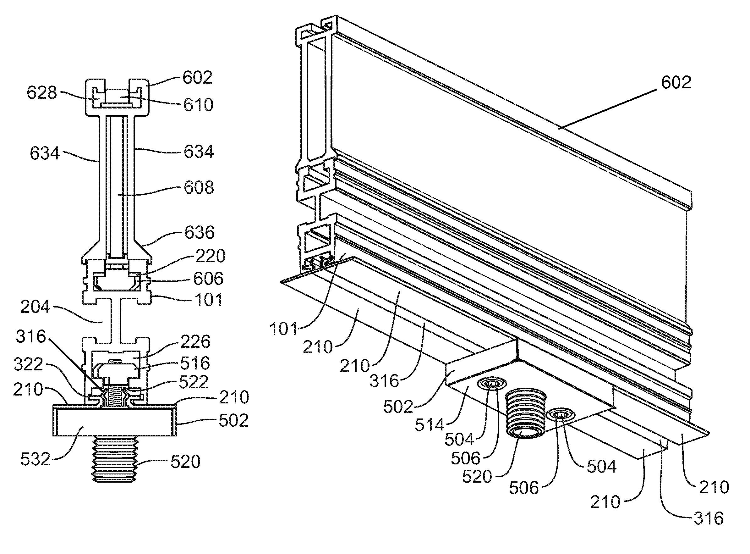
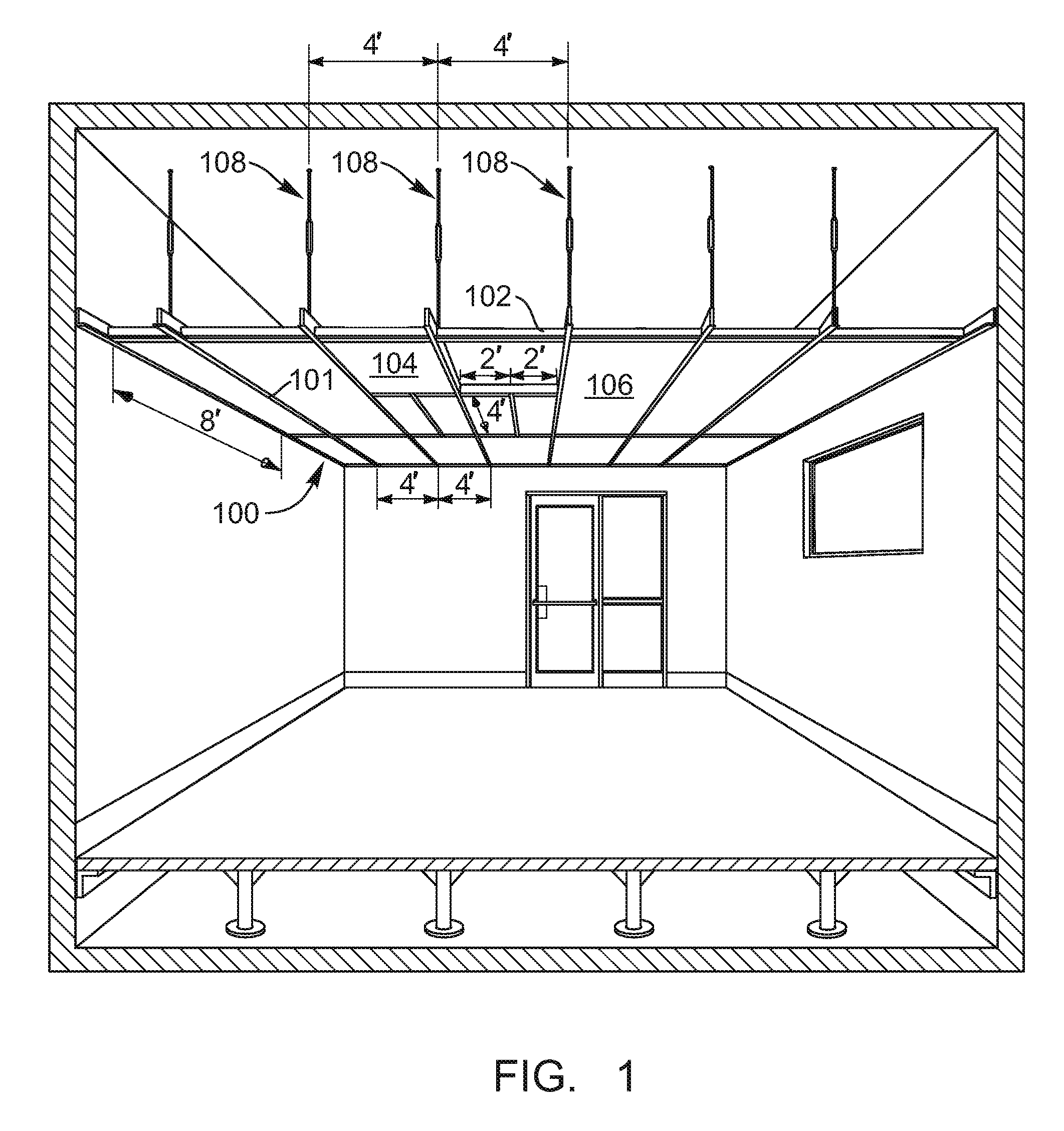
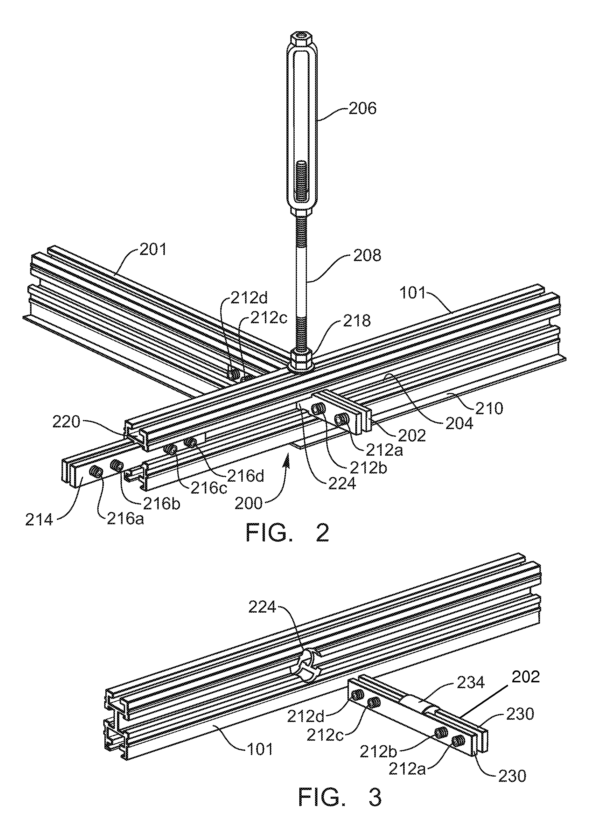
[0034]The extruded aluminum bottom-load ceiling is an extruded aluminum gasket tee bar ceiling. The pre-assembled cross tees are connected to the main tees using a cam-lock device that quickly locks the cross tees into position with a half turn of a ...


PUM


Abstract

An extruded aluminum bottom-load ceiling used in conjunction with cleanrooms comprises main tees and cross tees with removable flanges. The tees are connected via cam-lock devices or splice bars and may be hung on a 4′×4′ or 8′×8′ configuration. The tees also include hammerhead-nut slots used to suspend the tees from the building structure above and hang AMHS hangers from the tees. Grid stiffeners are included to increase the carrying capacity of the tees.

Description

RELATED APPLICATIONS[0001]This application is related to and claims priority from U.S. Provisional Patent Application Ser. No. 60 / 965,415 filed Aug. 20, 2007, for an Extruded Aluminum Bottom-Load Ceiling for Cleanrooms with Mechanism for Hanging Attachments, with inventor Peter J. Spransy which is incorporated herein by this reference.TECHNICAL FIELD[0002]The present invention relates to cleanroom ceilings. More specifically, it relates to cleanroom ceiling suspension systems from which you can drop a ceiling from a ceiling structure and suspend the ceiling with an interstitial space between the structure above and the bottom-load ceiling system.BACKGROUND[0003]Extruded aluminum ceilings are widely used in cleanrooms that perform semiconductor manufacturing processes. In such a ceiling, extruded aluminum members, shaped as inverted “tee”s, are hung from the building structure above, thus forming an interstitial space in between the ceiling and the building structure.[0004]Main tees ...

Claims


Application Information

Patent Timeline
IPC IPC(8): E04B9/18E04B9/00
CPCE04B9/006E04B9/064E04B9/127E04B9/183
Inventor SPRANSY, PETER J.
Owner AIRTEX MFG LLLP
Why Eureka
Try Eureka