Coded aperture imaging system having adjustable imaging performance with a reconfigurable coded aperture mask

a coded aperture and imaging system technology, applied in the field of coded aperture imaging system having a reconfigurable coded aperture mask, can solve the problem of increasing the signal to noise ratio, and achieve the effect of short timescale and larger effective pixels

Inactive Publication Date: 2011-02-15
QINETIQ LTD
View PDF102 Cites 24 Cited by
  • Summary
  • Abstract
  • Description
  • Claims
  • Application Information

AI Technical Summary

Benefits of technology

[0026]Another advantage of the present invention is that a coded aperture mask means, whether planar or curved, can be used to image through a curved or faceted surface that need not be hemispherical. The particular coded aperture array and processing algorithm used at any field of view can compensate for any differences in the optical effects of the curved surface at different fields of view. The use of a coded aperture imager arranged to image through a curved surface represents another aspect of the present invention and the invention also provides an imaging system having a coded aperture imager arranged to image through a non-planar element. The non-planar element obviously must be at least partially transmissive to radiation at the wavelength of operation and may, for example, comprise a window in a surface. As mentioned the non-planar element need not be hemispherical and indeed could be non-regular and yet the imaging system of this aspect of the invention will still produce an aberration free image. The coded aperture imager of this aspect of the invention comprises at least one detector and a coded aperture mask means and may conveniently be a coded aperture imager according to the first aspect of the invention. The non-planar element may form part of the external surface of a platform, such as an air vehicle, and may be aerodynamic in shape, i.e. the shape of the non-planar element is dictated mainly by aerodynamic considerations.
[0027]The reconfigurable coded aperture mask means of the first aspect of the invention may be any reconfigurable device which is capable of displaying a coded aperture array over at least part of its surface. The mask means may be pixilated and each pixel should be switchable between being transmissive and opaque. Note as used herein the term transmissive should be taken as meaning allowing at least some incident radiation at that pixel to pass from the mask toward the detector array and opaque should be read as blocking at least some incident radiation at that pixel from passing toward the detector array, with a transmissive pixel allowing significantly more radiation to reach the detector than an opaque pixel. The reconfigurable mask means could be a reflective device, such as a digital micro-mirror device, where the reflectivity of the pixels is altered to either reflect radiation from the scene to the detector array (transmissive) or not (opaque).
[0028]The reconfigurable coded aperture mas

Problems solved by technology

The small size of the apertures results in a high angular resolution but increasing the number of a

Method used


Image

  • Coded aperture imaging system having adjustable imaging performance with a reconfigurable coded aperture mask
  • Coded aperture imaging system having adjustable imaging performance with a reconfigurable coded aperture mask
  • Coded aperture imaging system having adjustable imaging performance with a reconfigurable coded aperture mask

Examples


Embodiment Construction

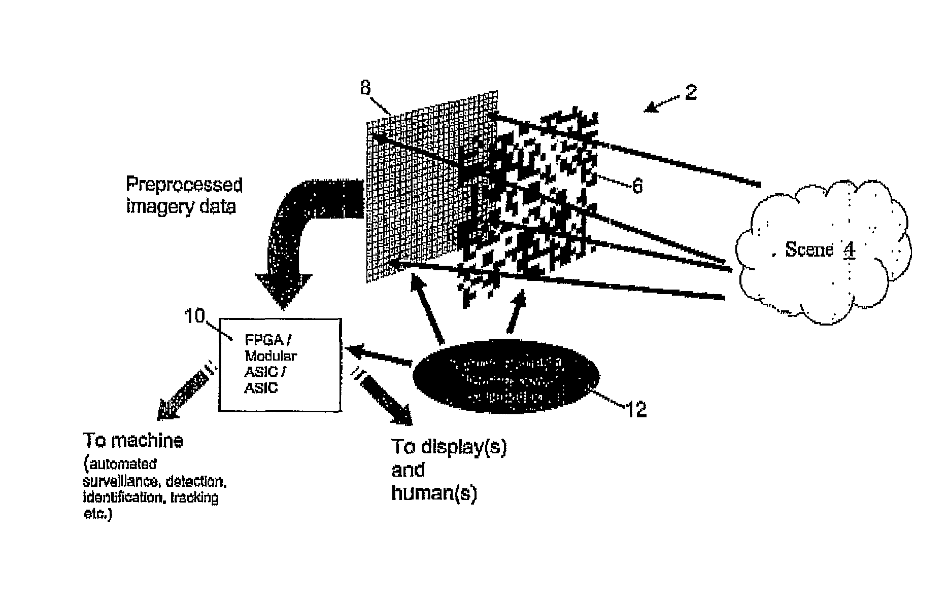
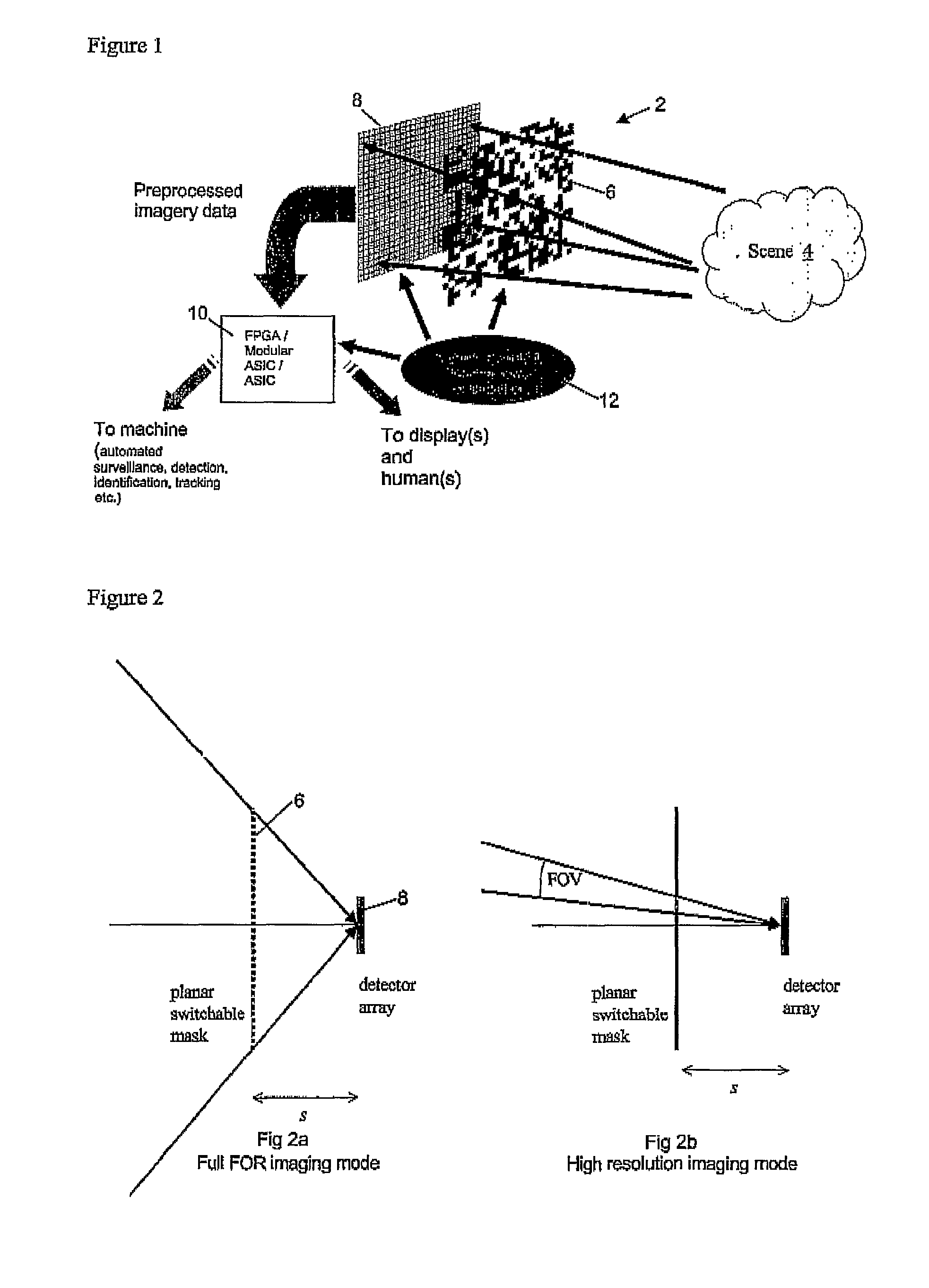
[0070]Conventional camera systems produce a focused image at the focal plane of its lens system, which effectively fixes the depth of the camera. In such systems, the focusing lens provides the required element of pre-detector processing by introducing a radially-varying phase shift, which enables an image to be produced by the time that the individual ray bundles have propagated to the focal plane of the lens. Fresnel diffractive lens systems and zone plates produce the necessary phase shifts using thinner structures, but still require the propagation of the individual ray bundles by the same distance. Conventional reflective and refractive lens systems constrain current camera designs and high performance systems are relatively bulky and costly to produce. The adaptability of such camera systems is also limited and steering the field of view for instance can involve moving bulky optical components with a large moment of inertia.

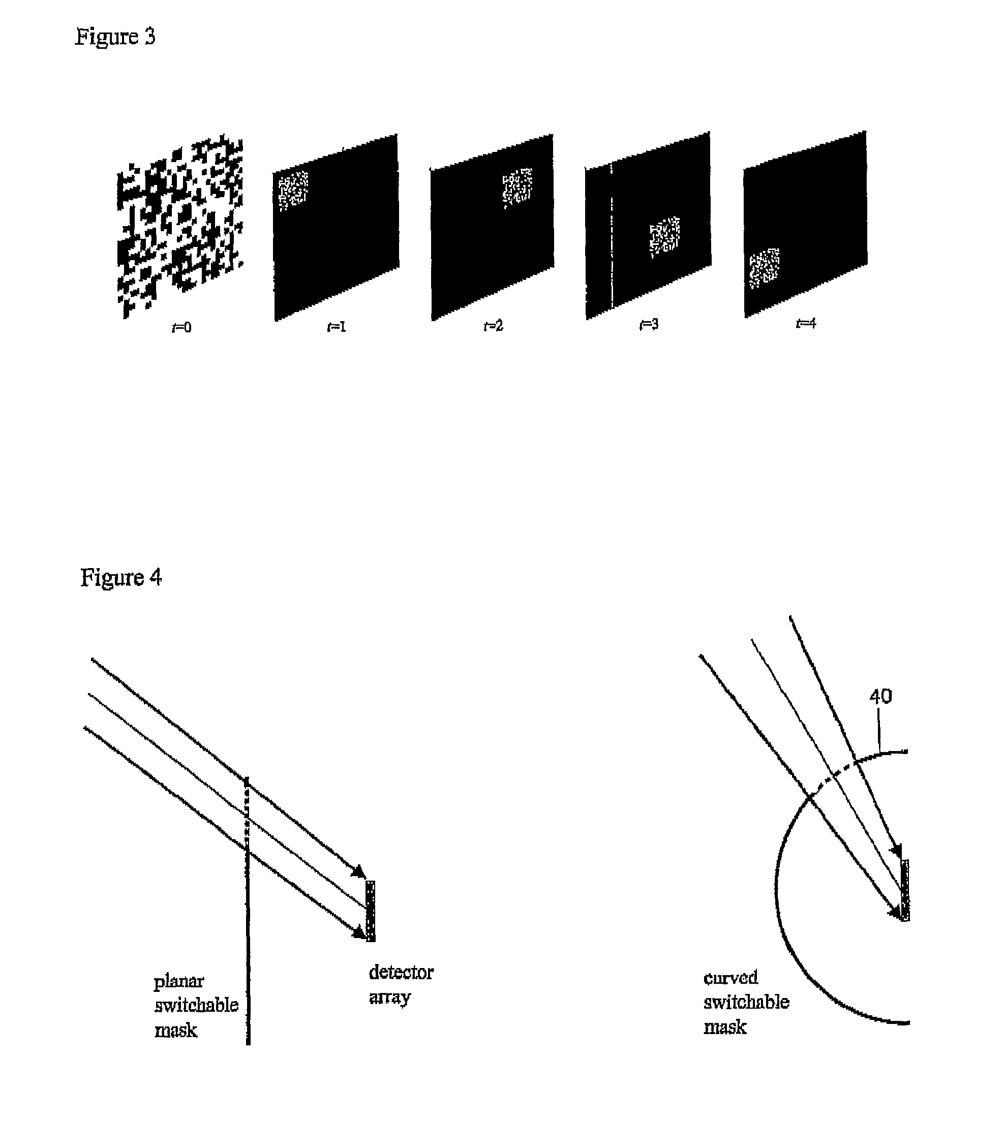
[0071]The present invention uses coded aperture imagi...


PUM


Abstract

This invention relates to coded aperture imaging apparatus and methods. In one aspect a coded aperture imager has at least one detector array and a reconfigurable coded aperture mask means. A reconfigurable coded aperture mask means can display various coded aperture masks to provide imaging across different fields of view and/or with different resolution without requiring any moving parts or bulky optical components. More than one detector array can be used to provide large area imaging without requiring seamless tiling and this represents another aspect of the invention. The present invention also relates to the use of coded aperture imaging in the visible, ultraviolet or infrared wavebands. The use of coded aperture imaging for imaging through a curved optical element is taught as the image decoding can automatically remove any aberrations introduced by the curved element.

Description

[0001]This application is the U.S. national phase of International Application No. PCT / GB2006 / 001890, filed 23 May 2006, which designated the U.S. and claims priority to Great Britain Patent Application No. 0510470.8, filed 23 May 2005, the entire contents of each of which are hereby incorporated by reference.BACKGROUND OF THE INVENTION[0002]1. Field of the Invention[0003]This invention relates to a coded aperture imaging system having a reconfigurable coded aperture mask, especially to an imaging system having adjustable imaging performance without requiring moving parts and to coded aperture imaging apparatus for operation at ultra violet, visible and infrared wavelengths.[0004]2. Discussion of Prior Art[0005]Optical systems for observing scenes are employed in a wide range of situations from CCTV security systems to surveillance / reconnaissance systems. Often these systems are required to be such that the imaging performance of the system can be adjusted, for example, in terms of ...

Claims


Application Information

Patent Timeline
IPC IPC(8): G01J3/50G01T1/29H04N5/225H04N5/33H04N5/335
CPCG01T1/295G02B27/00G06T1/0007H04N5/2259H04N5/335G02B2207/129H04N5/33H04N23/58H04N23/55H04N23/951H04N25/00G01T1/29G01B15/00
Inventor SLINGER, CHRISTOPHER WLEWIS, KEITH L
Owner QINETIQ LTD
Why Eureka
Try Eureka