Method for producing apertures in a diffuse reflector layer having a metal reflection film

a technology of metal reflection film and diffuse reflector, which is applied in the field of diffuse reflector type, can solve the problems of reducing the brightness produced by reflected light, reducing the efficiency of light collection, and not perfect positioning between the lenses and apertures, and achieves excellent visibility

Inactive Publication Date: 2011-02-15
RESONAC CORPORATION
View PDF14 Cites 5 Cited by
  • Summary
  • Abstract
  • Description
  • Claims
  • Application Information

AI Technical Summary

Benefits of technology

[0007]The technique disclosed in Japanese Patent Laid-Open Publication No. 2003-84276 can minimize the light blocked by the reflective film by focusing light onto the apertures using the microlenses installed between the back light and liquid crystal screen, but positioning between the lenses and apertures is not perfect and misalignment between the lenses and the centers of apertures can reduce light collection efficiency. Also, there is difference in shape between the apertures and focused portions. Consequently, the area of the reflective film is decreased in these parts, causing reduction in screen brightness produced by reflected light, and the light from the back light is blocked, causing a loss in transmitted light.
[0011]The present invention has an object to solve the above problems and provide a liquid crystal display of a transflective or other type with excellent visibility regardless of whether an external light or internal lighting source is used.
[0016]The present invention makes it possible to obtain a liquid crystal display of a transflective type with excellent visibility regardless of whether an external light or internal lighting source is used.

Problems solved by technology

The technique disclosed in Japanese Patent Laid-Open Publication No. 2003-84276 can minimize the light blocked by the reflective film by focusing light onto the apertures using the microlenses installed between the back light and liquid crystal screen, but positioning between the lenses and apertures is not perfect and misalignment between the lenses and the centers of apertures can reduce light collection efficiency.
Consequently, the area of the reflective film is decreased in these parts, causing reduction in screen brightness produced by reflected light, and the light from the back light is blocked, causing a loss in transmitted light.
However, the use of a diffusion reaction which takes place through a photomask made up of micro holes results in difficulty of lens profile control, making it a challenge to form an ideal curve.
Also, it is difficult to perform linear quadratic control of the microlenses and prepare lens arrays with different aspect ratios in order to correct a direction dependency of the light from the back light and viewing angle of the screen.
This makes it difficult to form the lenses on a liquid crystal display on which interconnects and the like have been formed.

Method used


Image

  • Method for producing apertures in a diffuse reflector layer having a metal reflection film
  • Method for producing apertures in a diffuse reflector layer having a metal reflection film
  • Method for producing apertures in a diffuse reflector layer having a metal reflection film

Examples


first embodiment

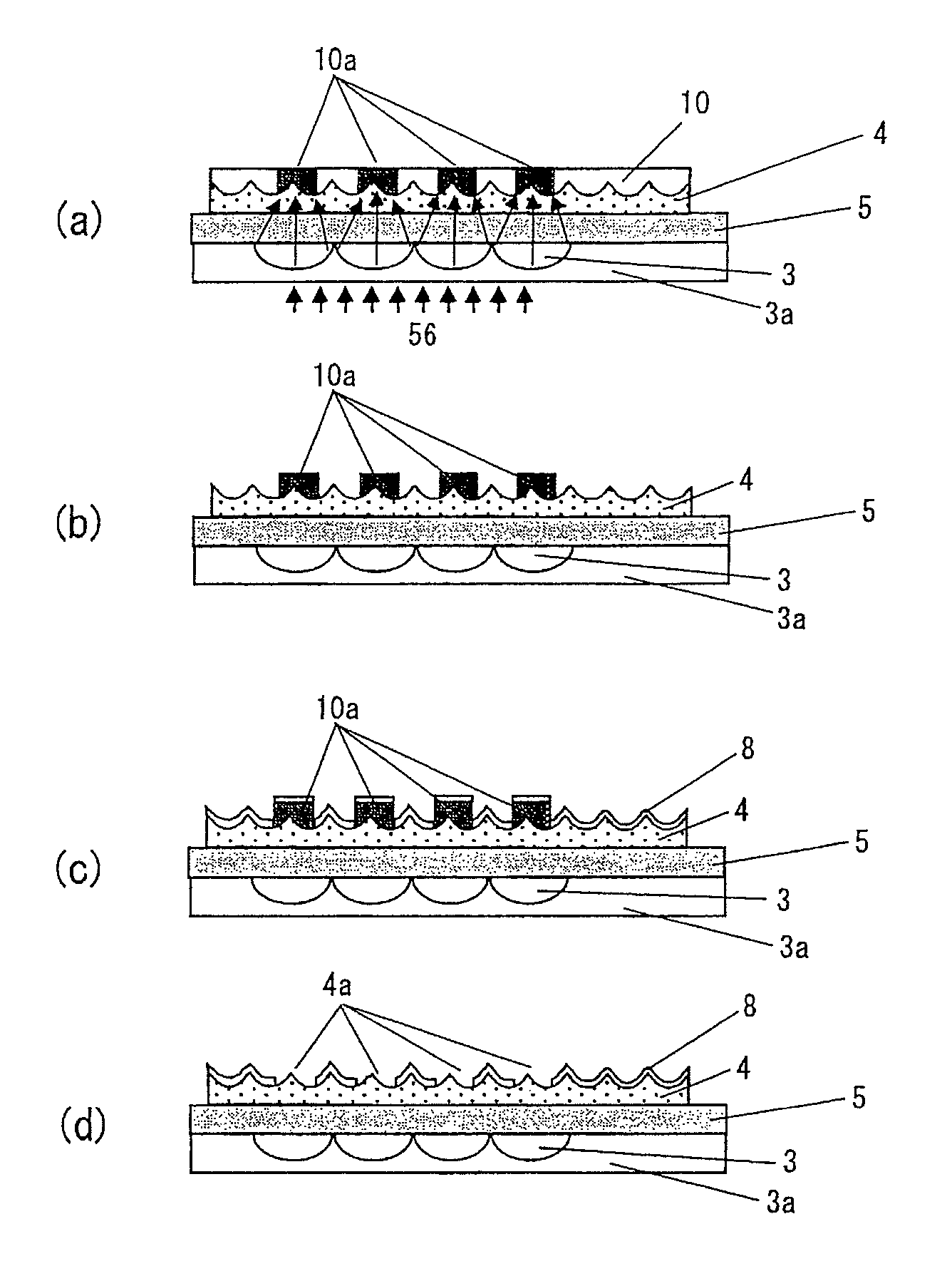
[0029]A first embodiment will be described. FIG. 1 is a sectional view of a transflective type liquid crystal display equipped with aperture-forming lenses and a diffuse reflector layer according to this embodiment. The liquid crystal display consists of display side members, a liquid crystal layer 7, and rear side members. The display side members include a color filter 9, a display side electrode 11, and an upper glass substrate 12. The liquid crystal layer 7 is interposed between the display side members and rear side members. The rear side members include aback light 1, a prism lens sheet 2, aperture-forming lenses 3, a flattening layer 3a, a diffuse reflector layer 4, a glass substrate 5, and a rear side electrode 6.

[0030]Apertures 4a are formed in the diffuse reflector layer 4. In the direction in which the light led from the back light 1 through the prism lens sheet 2 passes, the centers of the apertures 4a are coaxial with the center positions of the aperture-forming lenses ...

second embodiment

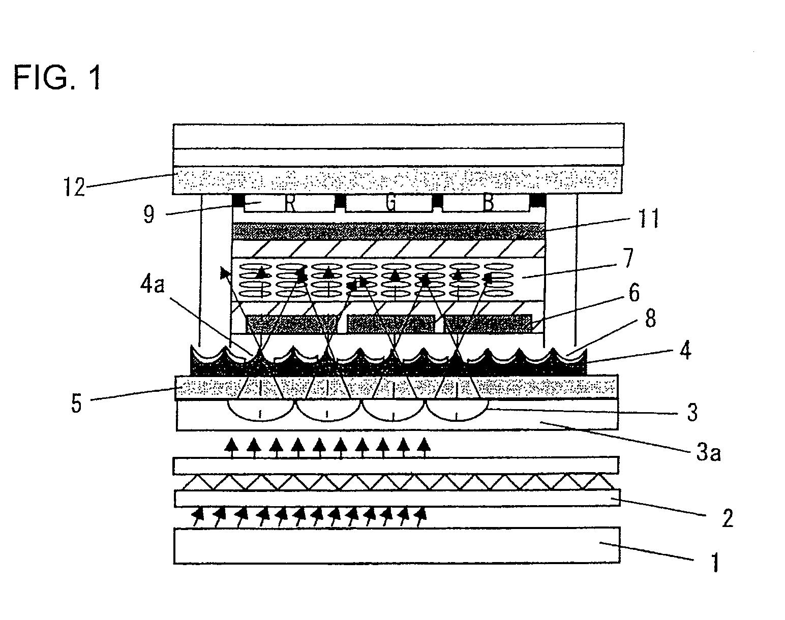
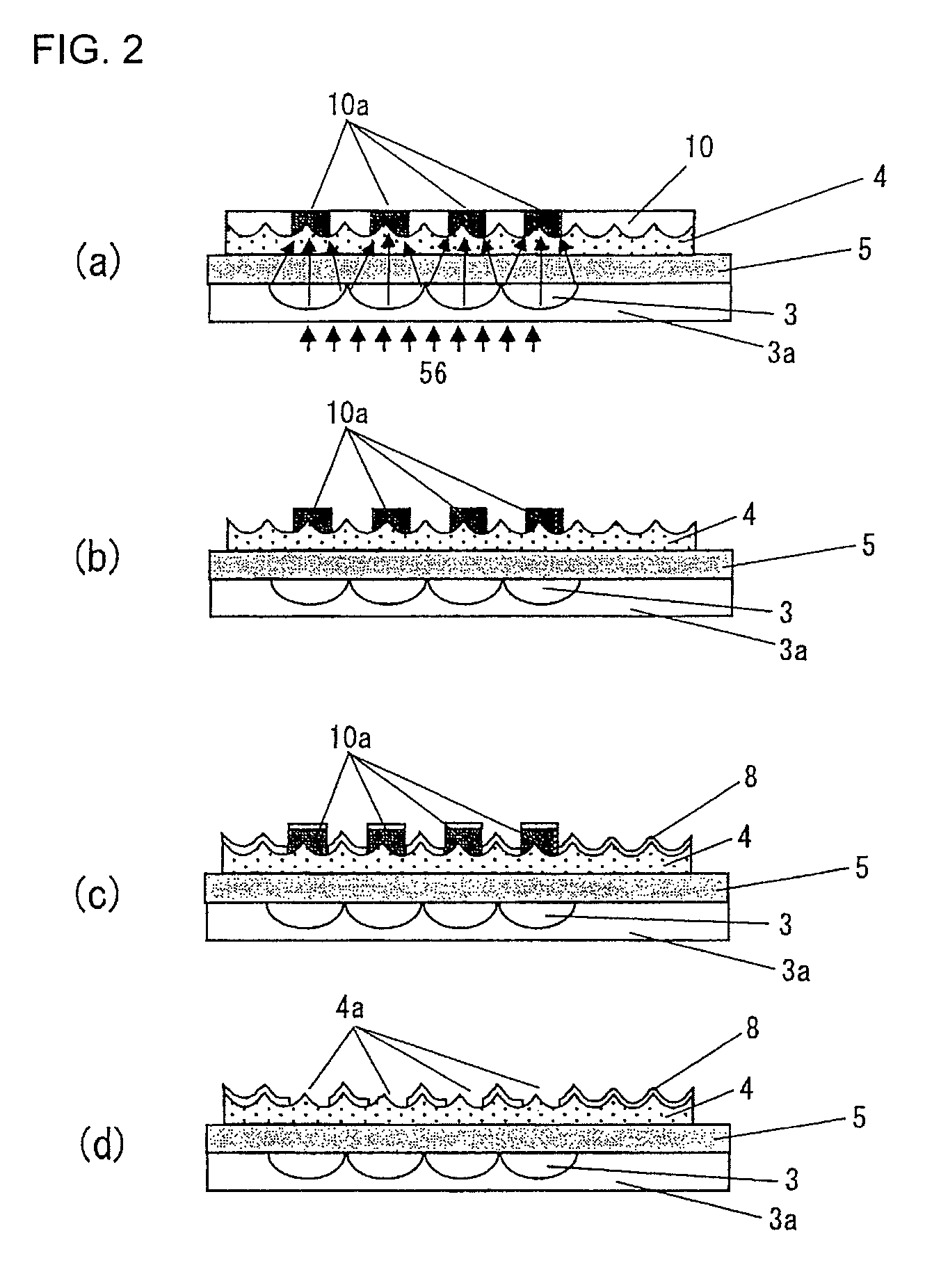
[0048]A second embodiment will be described with reference to FIG. 4. A liquid crystal display in FIG. 4 is the same as the one shown in FIG. 1 except that an aperture-forming lens-equipped film 20 is used instead of the aperture-forming lenses 3. The aperture-forming lens-equipped film 20 is pasted to the glass substrate 5. Since the film 20 is equipped with aperture-forming lenses 20a, it can collect light led from the back light 1 and pass it through the apertures in the diffuse reflector layer 4. Also, the aperture-forming lens-equipped film 20 has a flattening layer 20c under the aperture-forming lenses 20a to flatten a concave and convex pattern of the lenses.

[0049]FIG. 5 is an explanatory diagram illustrating a manufacturing process for forming the apertures 4a in the diffuse reflector layer 4 using the aperture-forming lens-equipped film 20. FIG. 5A shows the glass substrate 5 on which the diffuse reflector layer 4 is formed, where the upper surface of the diffuse reflector ...

third embodiment

[0053]A third embodiment will be described. This embodiment relates to a manufacturing method for an aperture-forming lens-equipped film. It will be described with reference to FIG. 6. FIG. 6 is a sectional view illustrating a process for manufacturing the aperture-forming lens-equipped film 20. FIG. 6A is a partial sectional view of a die used to manufacture the aperture-forming lens-equipped film 20. In FIG. 6A, lens-shaped concave curves 40a are cut on a surface of a die 40 using a cutting tool 41. Preferably, a diamond cutting tool is used as the cutting tool 41 because this will give superior surface roughness to the lens-shaped concave curves 40a of the die. As a result of the cutting, the die 40 is completed as shown in FIG. 6B.

[0054]The die 40 has the concave curves 40a. FIG. 6C is a sectional view of the aperture-forming lens-equipped film 20 consisting of the die 40, a microlens member 20a, and a base film 20b. The aperture-forming lens portion 20a installed on the base fi...


PUM

PropertyMeasurementUnit
thicknessaaaaaaaaaa
thicknessaaaaaaaaaa
thicknessaaaaaaaaaa

Abstract

A transflective type liquid crystal display has display side members; rear side members which include a diffuse reflector layer with apertures, and a glass substrate; and a liquid crystal layer interposed between the display side members and the rear side members, wherein on the opposite side from the diffuse reflector layer, the glass substrate has aperture-forming lenses used for exposure and removal during formation of the apertures of the diffuse reflector layer, and a flattening layer used to flatten a concave and convex surface produced by the aperture-forming lenses. This makes it possible to implement a transflective type liquid crystal display with excellent visibility regardless of whether an external light or internal lighting source is used.

Description

[0001]The present application is based on and claims priority of Japanese patent application No. 2006-010117 filed on Jan. 18, 2006, the entire contents of which are hereby incorporated by reference.BACKGROUND OF THE INVENTION[0002]The present invention relates to a liquid crystal display. More particularly, it relates to a transflective type liquid crystal display which provides good screen visibility in outdoor use such as under sunlight as well as in indoor use.[0003]Liquid crystal displays, which do not emit light by themselves in principle and display a screen using optical shutter effect caused by polarization, are roughly classified into three types according to the lighting source they use: transmissive type, reflection type, and transflective type.[0004]The transmissive type LCD has a back light at the back as a lighting source. The back light needs to be lit continuously for screen display and the screen cannot be displayed when the back light is off. The reflection type L...

Claims


Application Information

Patent Timeline
Patent Type & Authority Patents(United States)
IPC IPC(8): G02F1/13
CPCG02B5/021G02B5/0268G02B5/0284G02F1/133504G02F1/133555G02F2001/133567G02F1/133567G02B5/02G02F1/1335
Inventor YOSHIKAWA, TAKEHISAKYOI, MASAYUKISUGIMOTO, YASUSHITAYA, MASATOYOSHIDA, TAKESHI
Owner RESONAC CORPORATION
Why Eureka
Try Eureka