Insert for drill and indexable insert drill

a drill and insert drill technology, applied in the direction of cutting inserts, twist drills, manufacturing tools, etc., can solve the problems of easy loss of cutting edge, deterioration of surface quality of inner wall surface of machining holes, and degradation of surface quality, etc., to prolong the life of inserts, improve the quality of inserts, and improve the effect of machining quality

Active Publication Date: 2011-02-22
MITSUBISHI MATERIALS CORP
View PDF11 Cites 8 Cited by
  • Summary
  • Abstract
  • Description
  • Claims
  • Application Information

AI Technical Summary

Benefits of technology

[0012]Meanwhile, in the outer peripheral insert, the wiper edge of the other single cutting edge adjacent to the radial outer peripheral side of a single cutting edge directed to the tip is formed in the shape of a straight line, and disposed so as to extend to a direction of the axis of the drill body. Thus, the inner wall surface of a machining hole can be finished by the wiper edge, and thereby, high surface quality can be secured in the inner wall surface. Moreover, since the wiper edge and the second major cutting edge portion of the major cutting edge is disposed in a direction in which they intersect each other at an obtuse angle, the intersection portion does not interfere with the inner wall surface of a machining hole.
[0014]Additionally, the length of the convex curve chord formed by the first major cutting edge portion is set to the range of 0.3×IC to 0.7×IC with respect to the diameter IC of a circle inscribed in this rake face, in plan view. If the length of the chord is smaller than this range, the circular-arc first cutting edge portion becomes small in the major cutting edge. Therefore, there is a possibility that a loss may occur at the time of contact to a work material. On the other hand, if the length of the chord is greater than this range, the distance of protrusion from the imaginary plane of the first major cutting edge portion toward the tip becomes large in the inner peripheral insert. Therefore, the distance by which only the inner peripheral indexable insert drills a work material at the time of contact also becomes large. Thus, balance is upset, and radial run out also occurs easily.
[0017]Meanwhile, in the indexable insert drill of the second aspect of the invention, preferably, the distance in the direction of the axis of the drill body between a protruding end of the first major cutting edge portion of the single cutting edge in the direction of the axis of the drill body in the inner peripheral insert, and an extreme end of the wiper edge of the single cutting edge in the direction of the axis of the drill body in the outer peripheral insert is set to 0.05 mm to 0.3 mm. If the distance is smaller than the above range, and if the amount of feed of the drill body is large, the wiper edge of the single cutting edge directed toward the tip of the outer peripheral insert is greatly involved in cutting, whereby wear or the like occurs, there is a possibility that the wiper edge cannot be used for finishing of the inner wall surface of a machining hole. On the other hand, if the distance is greater than this range, the distance of protrusion of the first major cutting edge portion in the inner peripheral insert becomes large. As a result, there is a possibility that the distance by which only the inner peripheral indexable insert drills a work material at the time of contact also becomes long, and thus, radial run out also occurs easily.
[0018]Preferably, the second major cutting edge portion of the single cutting edge in the radial inner peripheral insert is made to intersect the imaginary plane at an intersection angle of 3° to 8°. If the intersection angle is too small, the straight second major cutting edge portion contacts a work material largely along with the first major cutting edge portion at the time of contact, whereby radial run out may easily occur. On the other hand, if the intersection angle is too large, there is a possibility that the portion of the first major cutting edge portion of the major cutting edge on the side of the corner cutting edge in the single cutting edge of the inner peripheral insert, or the corner cutting edge itself is greatly involved in cutting at the time of contact or at the time of drilling, whereby a loss may easily occur.
[0020]As described above, according to the insert for a drill of the first aspect of the invention and the indexable insert drill of the second aspect to which this insert is attached, a loss does not occur in the cutting edges at the time of contact with a work material, the lifespan of an insert can be extended, and smooth drilling can be performed. Additionally, radial run out can be prevented from occurring in the drill body at the time of contact, and the inner wall surface of a machining hole can be finished with high surface quality. Thus, it is possible to form a machining hole which has excellent roundness, concentricity, and cylindricity, and has a high degree of precision. Additionally, since an insert for a drill with an insert body of the same dimension and shape is attached to inner and outer peripheries of the tip of the drill body, insert management can be simplified and efficient.

Problems solved by technology

Therefore, loss of the cutting edge may easily occur.
Therefore, when the amount of feed is increased, there is also a possibility that the surface quality of the inner wall surface of a machining hole may deteriorate.
In this case, when such a cutting edge is directed toward the outer peripheral side of the drill body in the radial outer peripheral insert for a drill, there is a possibility that the step may interfere with the inner wall surface of a machining hole, and degradation of surface quality may also occur.
Thus, a large impact occurs, and balance is easily upset.
Therefore, there is also a possibility that management may become complicated, and erroneous attachment of the inserts may occur at the inner and outer peripheries.

Method used


Image

  • Insert for drill and indexable insert drill
  • Insert for drill and indexable insert drill
  • Insert for drill and indexable insert drill

Examples


Embodiment Construction

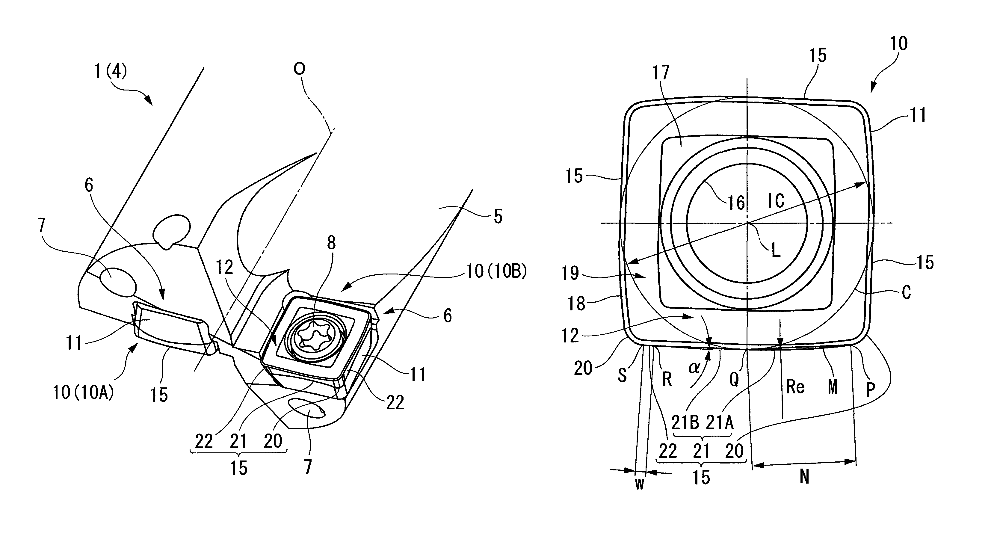
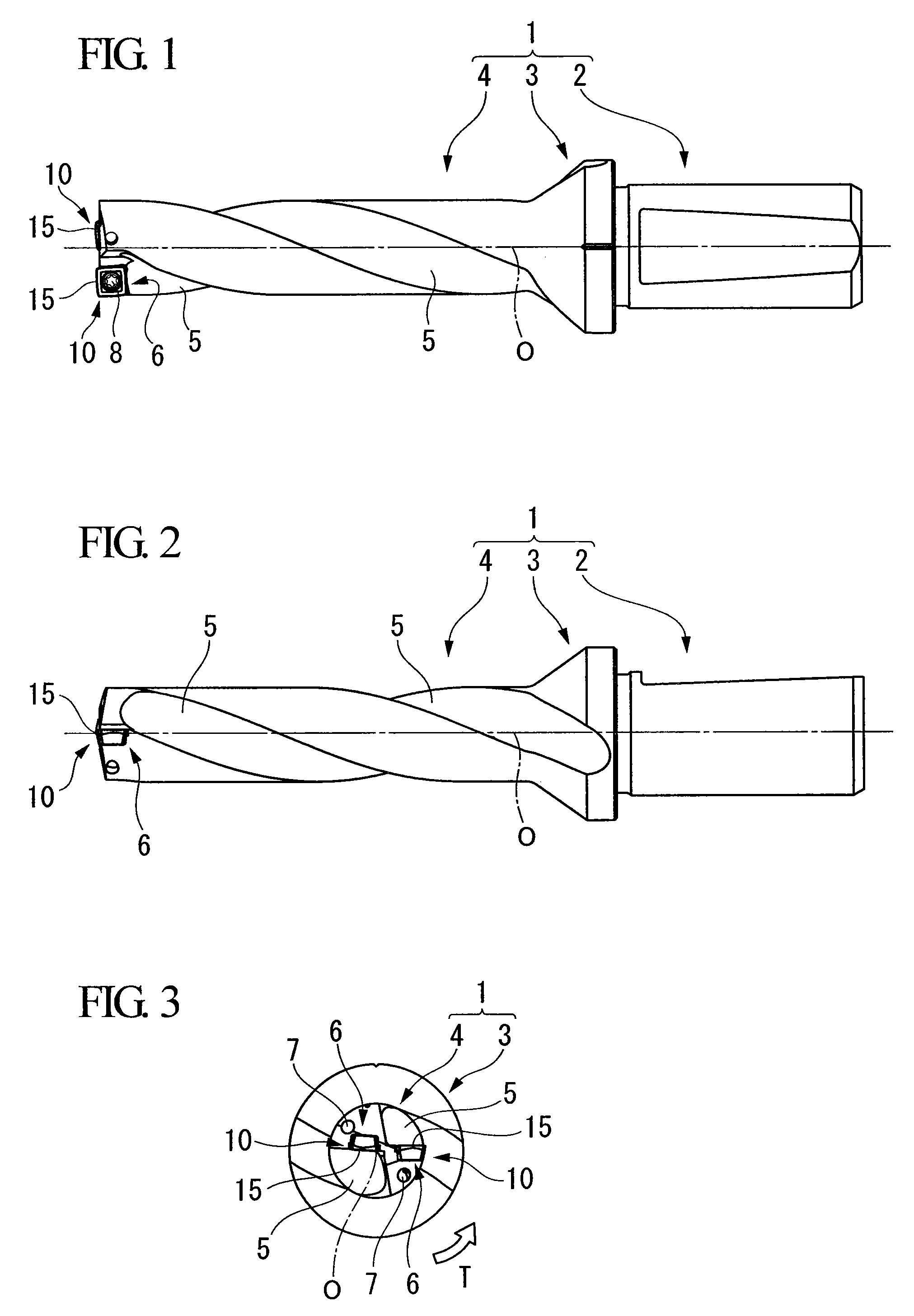
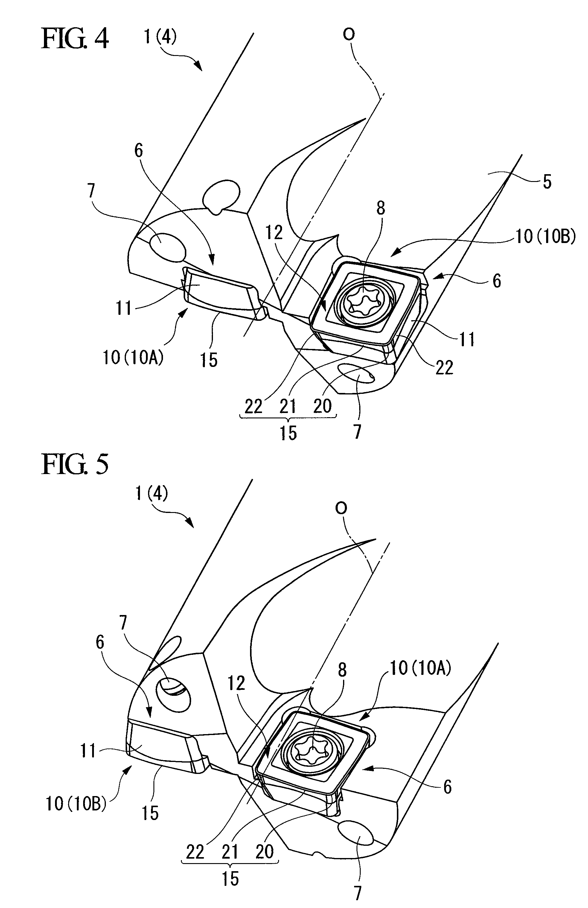
[0030]FIGS. 1 to 9 show one embodiment of the invention. Among these drawings, FIGS. 1 to 5 show an indexable insert drill of this embodiment, and FIGS. 6A, 6B, 7 and 8 show an insert of this embodiment. In the indexable insert drill of this embodiment, a drill body 1 is formed from steel or the like and is formed in a substantially cylindrical shape having an axis O as its center. A rear end portion (a right portion in FIGS. 1 and 2) of the drill body is used as a shank portion 2, and a tip portion (a left portion in FIGS. 1 and 2) of the drill body is used as a cutting portion 4 via a flange 3. The shank portion 2 is gripped by a spindle of a machine tool, is rotated in a drill rotational direction T around the axis O (a counterclockwise direction as shown in FIG. 3 as seen from the tip in the direction of the axis O in this embodiment), and is used for drilling a work material.

[0031]In the cutting portion 4, a pair of chip discharge grooves 5, which is twisted backward in the dri...


PUM

PropertyMeasurementUnit
lengthaaaaaaaaaa
angleaaaaaaaaaa
intersection angleaaaaaaaaaa

Abstract

An insert for a drill in which one of the cutting edges respectively formed at four side ridge portions of a rake face of a square flat plate-shaped insert body is made to protrude toward the tip of the drill body of the indexable insert drill while being detachably attached is provided. Each of the cutting edges has a corner cutting edge located at a corner of the rake face, and a major cutting edge and a wiper edge which extend substantially toward one peripheral direction of the rake face from a corner cutting edge. The major cutting edge has a first major cutting edge portion which has a convexly curved shape and extends from the corner cutting edge, and a second major cutting edge portion which smoothly touches the first major cutting edge portion and extends linearly, as seen from a direction facing the rake face. The wiper edge has a straight shape intersecting the second major cutting edge portion at an obtuse angle.

Description

BACKGROUND OF THE INVENTION[0001]1. Field of the Invention[0002]The present invention relates to an insert for an indexable insert drill attached to an insert detachable drill, and an indexable insert drill to which the insert for an indexable insert drill is attached. Priority is claimed on Japanese Patent Application No. 2008-089679, filed Mar. 31, 2008, the content of which is incorporated herein by reference.[0003]2. Description of Related Art[0004]As an insert for a drill and an indexable insert drill, a drill in which substantially square flat plate-shaped inserts for a drill are detachably attached to the tip of a drill body on the radial inner peripheral side and outer peripheral side which are opposite to each other across the axis of the drill body is disclosed in, for example, Japanese Patent Examined Patent Application, Second Publication No. Sho 53-15234 and Published Japanese Translation No. 2005-527390 of PCT International Publication. In such an indexable insert dril...

Claims


Application Information

Patent Timeline
Patent Type & Authority Patents(United States)
IPC IPC(8): B23B27/16B23B51/00
CPCB23B27/145B23B51/048B23B2200/0471B23B2200/125Y10T407/19B23B2200/208B23C2270/06Y10T407/235Y10T407/1924B23B2200/204B23B51/00B23B2251/50B23B27/1603B23B27/1611B23B51/02
Inventor TAKAHASHI, HIDEBUMINARITA, TOURU
Owner MITSUBISHI MATERIALS CORP
Why Eureka
Try Eureka