Supercharge Your Innovation With Domain-Expert AI Agents!

Multilayer film, electrooptic device, electronic apparatus, and process for forming multilayer film

a multi-layer film and electrooptic technology, applied in the field of multi-layer film, electrooptic device, electronic apparatus, and can solve the problems of insufficient improvement of adhesion and contact properties between layers, known process for forming multi-layer film by droplet discharge method, etc., to achieve convenient formation of liquid layer, effective redissolving of the surface of the solid lower layer, and satisfactory adhesion and contact properties

Inactive Publication Date: 2011-02-22
SEIKO EPSON CORP
View PDF17 Cites 0 Cited by
  • Summary
  • Abstract
  • Description
  • Claims
  • Application Information

AI Technical Summary

Benefits of technology

The process results in multilayer films with enhanced adhesion and contact properties, leading to improved reliability and functional efficiency of electrooptic devices and electronic apparatuses by increasing the contact area between layers and reducing interface resistance.

Problems solved by technology

However, the known process for forming the multilayer film by the droplet discharge method is not sufficient for the improvement of the adhesion and contact properties between the layers.

Method used


Image

  • Multilayer film, electrooptic device, electronic apparatus, and process for forming multilayer film
  • Multilayer film, electrooptic device, electronic apparatus, and process for forming multilayer film
  • Multilayer film, electrooptic device, electronic apparatus, and process for forming multilayer film

Examples


first embodiment

Electrooptic Device

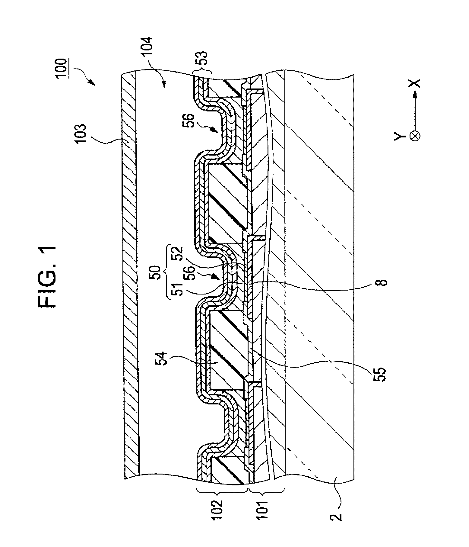
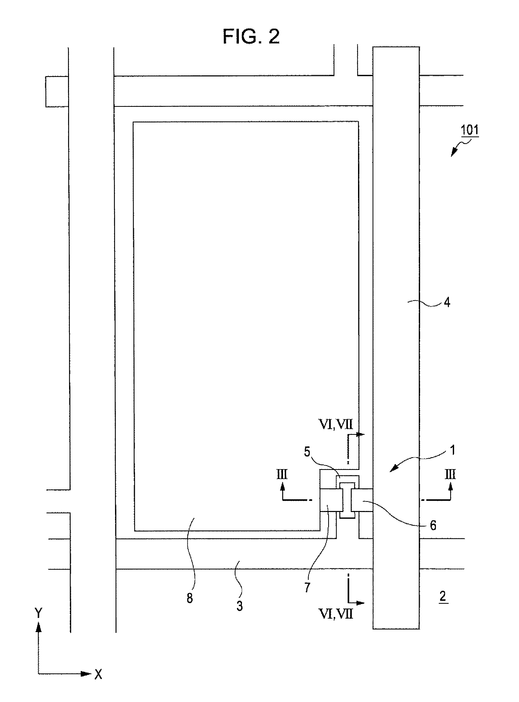
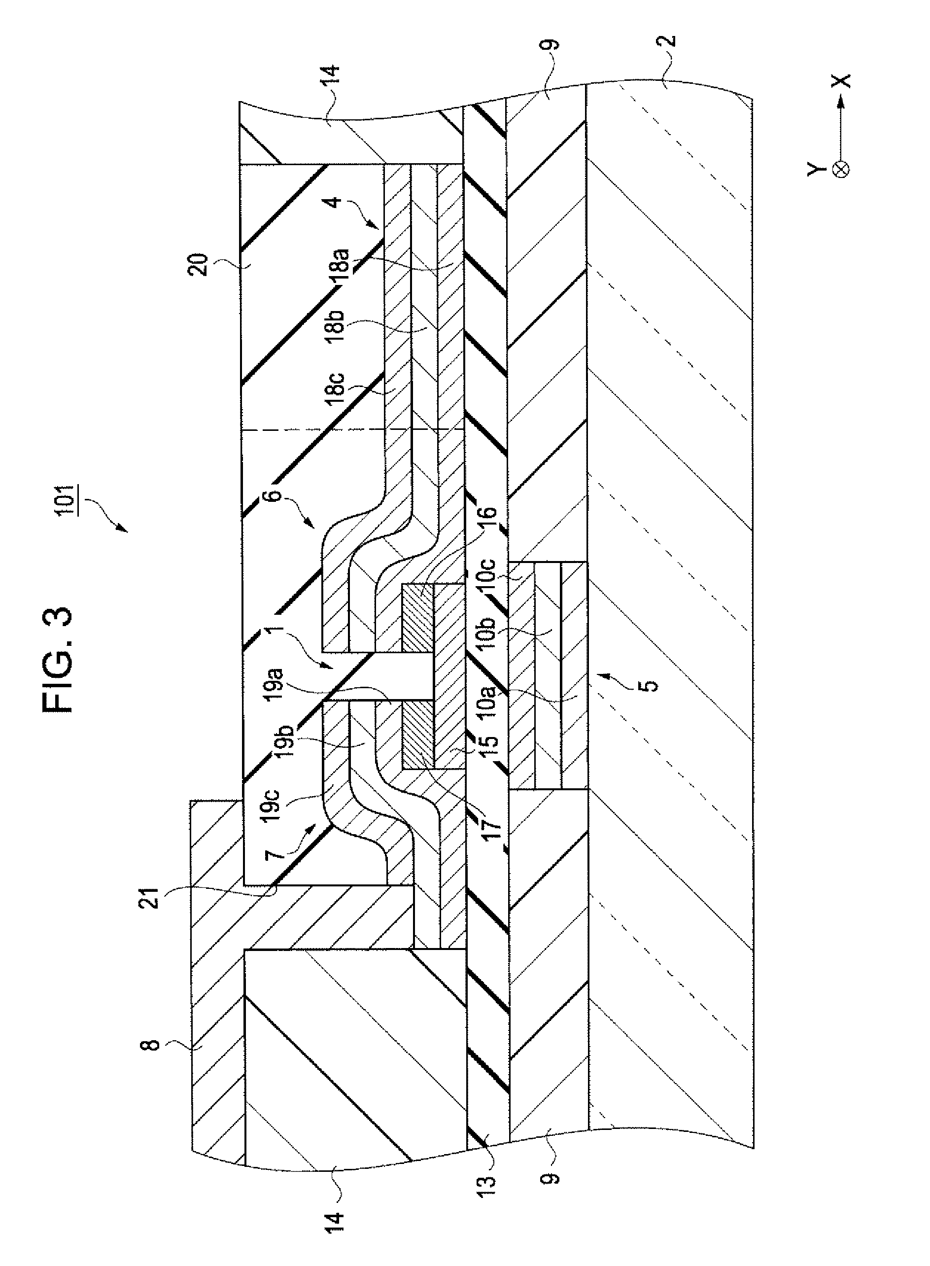
[0039]An electrooptic device in accordance with the invention will be described with reference to FIGS. 1, 2, and 3. FIG. 1 is a fragmentary cross-sectional view of the electrooptic device in accordance with an embodiment of the invention. FIG. 2 is a plan view of the driving circuit portion of the electrooptic device. FIG. 3 is a cross-sectional view of a driving element and its peripheral structure, the view being taken along the line III-III in FIG. 2.

[0040]As shown in FIG. 1, an electrooptic device 100 includes an elemental substrate 2, a driving circuit portion 101 on the elemental substrate 2, a luminescent element portion 102 on the driving circuit portion 101, and a sealing substrate 103 for sealing the driving circuit portion 101 and the luminescent element portion 102, the sealing substrate 103 being remote from the elemental substrate 2. The elemental substrate 2 is preferably a glass substrate. A sealed cavity 104 sealed with the sealing substrate 103 ...

second embodiment

[0083]Referring now to FIG. 11, a second embodiment of the invention will be described. FIG. 11 is a schematic perspective view of a fuel cell in accordance with an embodiment of the invention.

[0084]A fuel cell 120 shown in FIG. 11 generates electric power by reaction of a hydrogen gas and an oxygen gas. The fuel cell 120 has a structure in which a multilayer film 130 is disposed between two substrates 121 and 122 having gas channels 121a and 122a, respectively, the multilayer film 130 including electrode layers 128 and 129, gas diffusion layers 123 and 124, catalytic layers 125 and 126, and an ion-exchange layer 127. The electrode layers 128 and 129 are each composed of a conductive material such as copper. The gas diffusion layers 123 and 124 are each composed of porous carbon and the like. The catalytic layers 125 and 126 are each composed of platinum and the like. The ion-exchange layer 127 is composed of an ion-conducting electrolyte, such as Nafion® (manufactured by Du Pont Ka...


PUM


Abstract

A process for forming a multilayer film includes (a) discharging a first functional liquid containing a first functional material on a substrate by a droplet discharge method to form a lower layer, (b) solidifying the first functional liquid on the substrate to form a solid lower layer containing the first functional material, (c) forming a liquid layer containing the first functional material on the solid lower layer, (d) discharging a second functional liquid containing a second functional material on the liquid layer and the solid lower layer by the droplet discharge method to form an upper layer, and (e) solidifying the liquid layer and the second functional liquid to form a solid upper layer.

Description

BACKGROUND[0001]1. Technical Field[0002]The present invention relates to a multilayer film, an electrooptic device, an electronic apparatus, and a process for forming the multilayer film.[0003]2. Related Art[0004]In recent years, film-forming techniques employing droplet discharge methods, i.e., inkjet methods, have been used in the production of interconnections and functional elements. In a known film-forming technique, a functional film is formed by disposing a liquid (functional liquid) containing a functional material on a substrate with a drawing device such as an inkjet printer to form a pattern; and performing drying or the like on the disposed functional liquid. Such a film-forming technology can be applied to high-mix low-volume production and is significantly effective.[0005]In the production of a functional element or the like by the film-forming technique, a plurality of types of functional films can be laminated by successively repeating the drawing and drying steps. F...

Claims


Application Information

Patent Timeline
Patent Type & Authority Patents(United States)
IPC IPC(8): B05D5/12B05D1/38B05D3/10
CPCH05K3/4664H05K3/125H05K3/245H05K2203/1476H05K2203/013H05B33/10
Inventor HASEI, HIRONORIINAGAKI, AKIRA
Owner SEIKO EPSON CORP
Features
  • R&D
  • Intellectual Property
  • Life Sciences
  • Materials
  • Tech Scout
  • Unparalleled Data Quality
  • Higher Quality Content
  • 60% Fewer Hallucinations
Learn More