
Dynamic replanning algorithm for aircrew display aid to assess jam effectiveness

a dynamic replanning algorithm and aircrew technology, applied in the field of computer software, can solve the problems of reducing the performance of low-technology threat receivers, affecting the performance of noise jamming approaches, and current systems being incapable of fusing ea jamming capability with projected threat emitter performance information, etc., to achieve rapid assessment of current and future jamming effectiveness.

Inactive Publication Date: 2011-02-22
THE UNITED STATES OF AMERICA AS REPRESENTED BY THE SECRETARY OF THE NAVY
View PDF28 Cites 12 Cited by
  • Summary
  • Abstract
  • Description
  • Claims
  • Application Information

AI Technical Summary

Benefits of technology

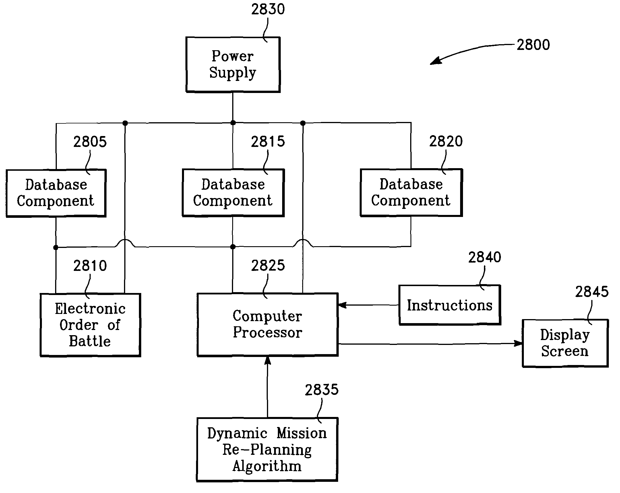
[0009]For the EA to determine its optimal future (look-ahead) position it must continually ascertain an extrapolated position of the PE in relationship to each threat emitter and mathematically generate a Jam Acceptability Region (JAR) as well as its own position within the JAR. The DMR portion of the Jam Assessment software program must account for the interaction of the JAR and the PE position as the PE transits its flight path. The DMR portion of the Jam Assessment software program processes or blends the extrapolated future position of the EA aircraft and PE aircraft with the information residing in an electronic library designated as an Electronic Order of Battle (EOB). The positional and EOB information processed by the DMR portion of the Jam Assessment software program is used by the Display Management routine to generate the graphical cues and text for display in a user selectable format allowing a rapid assessment of current and future jamming effectiveness.

Problems solved by technology

Barrage noise jamming floods the threat radar receiver with massive amounts of electronic emissions and significantly degrades low technology threat receiver performance.
With the evolution of advanced radar concepts the noise jamming approach is less effective against high technology threat emitters.
Current systems are incapable of fusing EA jamming capability with projected threat emitter performance information in order to obtain optimal geometrical positioning of the EA relative to threat emitters.

Method used


Image

  • Dynamic replanning algorithm for aircrew display aid to assess jam effectiveness
  • Dynamic replanning algorithm for aircrew display aid to assess jam effectiveness
  • Dynamic replanning algorithm for aircrew display aid to assess jam effectiveness

Examples


Embodiment Construction

[0045]The present invention comprises a method and computer implemented software module that efficiently and simultaneously receives disparate information and transforms the disparate information into a series of graphical and textual display formats. The graphical and textual displays convey information useful to position the EA relative to a threat emitter system. A typical threat emitter system, such as a radar, is composed of an antenna, a transmitter, a receiver, electronics to process information received and a user interface. Key to the success of any radar jamming technique is exceeding the Signal to Noise ratio threshold that is an inherent characteristic of the threat emitter system. When the noise signal generated by the EA exceeds the signal return of the PE the threat emitter system is defeated. Likewise, if the EA generates a stronger yet similar signal to the actual return signal of the PE while shifting a PE parameter, such as range or speed, the threat emitter syste...


PUM


Abstract

The invention generally relates to the field of computer software particularly to an improved method of providing aircrew decision aids for use in determining the optimum placement of an Electronic Attack (EA) aircraft. The core of the invention is a software program that will dynamically provide the EA flight crew situational awareness regarding a threat emitter's coverage relative to the position of the EA aircraft and to the position of any number of protected entities (PE). The software program generates information to provide visual cues representing a Jam Acceptability Region (JAR) contour, a Jam Assessment Strobe (JAS) and text for display on a number of flexibly configurable display formats posted on display units. The JAR and JAS graphics and text will aid the EA aircrew in rapidly assessing the effectiveness of a given jamming approach. It is emphasized that this abstract is provided to comply with the rules requiring an abstract that will allow a searcher or other reader to quickly ascertain the subject matter of the technical disclosure. It is submitted with the understanding that it will not be used to interpret or limit the scope of the claims.

Description

CROSS-REFERENCE TO RELATED APPLICATIONS[0001]This application claims priority under 35 U.S.C. §120 and is a continuation-in-part of U.S. patent application Ser. No. 11 / 901,545, now U.S. Pat. No. 7,515,096, filed Sep. 12, 2007, which is a continuation-in-part of U.S. patent application Ser. No. 11 / 820,033, now U.S. Pat. No. 7,427,947 filed May 30, 2007, the entire disclosures of which are incorporated herein by reference.STATEMENT REGARDING FEDERALLY SPONSORED RESEARCH OR DEVELOPMENT[0002]The invention described herein may be manufactured and used by or for the government of the United States of America for governmental purposes without the payment of any royalties thereon or therefore.BACKGROUND OF THE INVENTION[0003]1. Field of the Invention[0004]The invention relates to the field of computer software and particularly to an improved method for displaying aircrew decision aids for use in determining the optimum placement of an Electronic Attack (EA) aircraft. The core of the inventi...

Claims


Application Information

Patent Timeline
Patent Type & Authority Patents(United States)
IPC IPC(8): G01S7/38G01S7/40G01S7/00G01S13/00
CPCG01S7/021G01S7/04G01S7/38H04K3/45H04K3/94H04K2203/22
Inventor DARK, JAMESBUSCEMI, JAMESBURKHOLDER, SCOTT
Owner THE UNITED STATES OF AMERICA AS REPRESENTED BY THE SECRETARY OF THE NAVY
Learn More