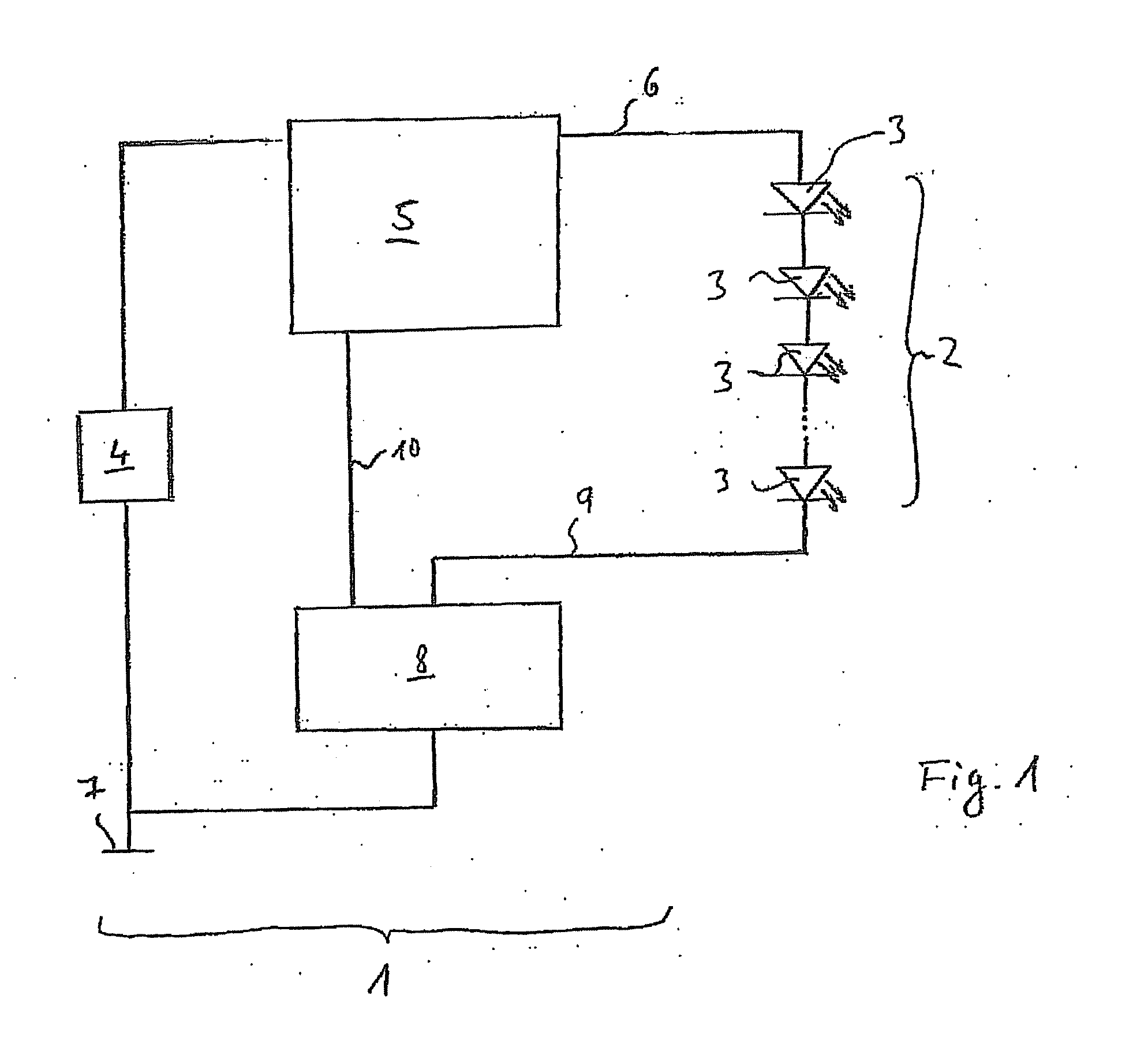
[0003]An example drive device according to the present invention may have the
advantage that on the one hand a high degree of
operational reliability is achieved, and on the other hand
power loss is minimized. These advantages may be achieved due to the fact that not only the
operating voltage of the light-emitting diodes but also the current flowing through the light-emitting diodes is regulated. As a result of the current regulation, first of all it is possible to prevent destruction of the light-emitting diodes due to an excessively
high current flow. If unexpectedly strong increases in voltage, voltage fluctuations, or other types of disturbances in voltage generation occur, the current regulation may be used to directly and promptly limit the current conducted through the light-emitting diodes in order to prevent destruction of the light-emitting diodes on account of excessively high current flow. By using the current regulation it is also possible to continuously adjust the voltage until the exact amount of necessary current is able to flow through the series circuit of the light-emitting diodes. This results in an
operating point which is close to the minimum possible power loss. In addition, during manufacture of the overall lighting unit the production tolerances of the light-emitting diodes do not have to be compensated, or may be compensated in a less complex way, thereby simplifying the manufacture of such units.
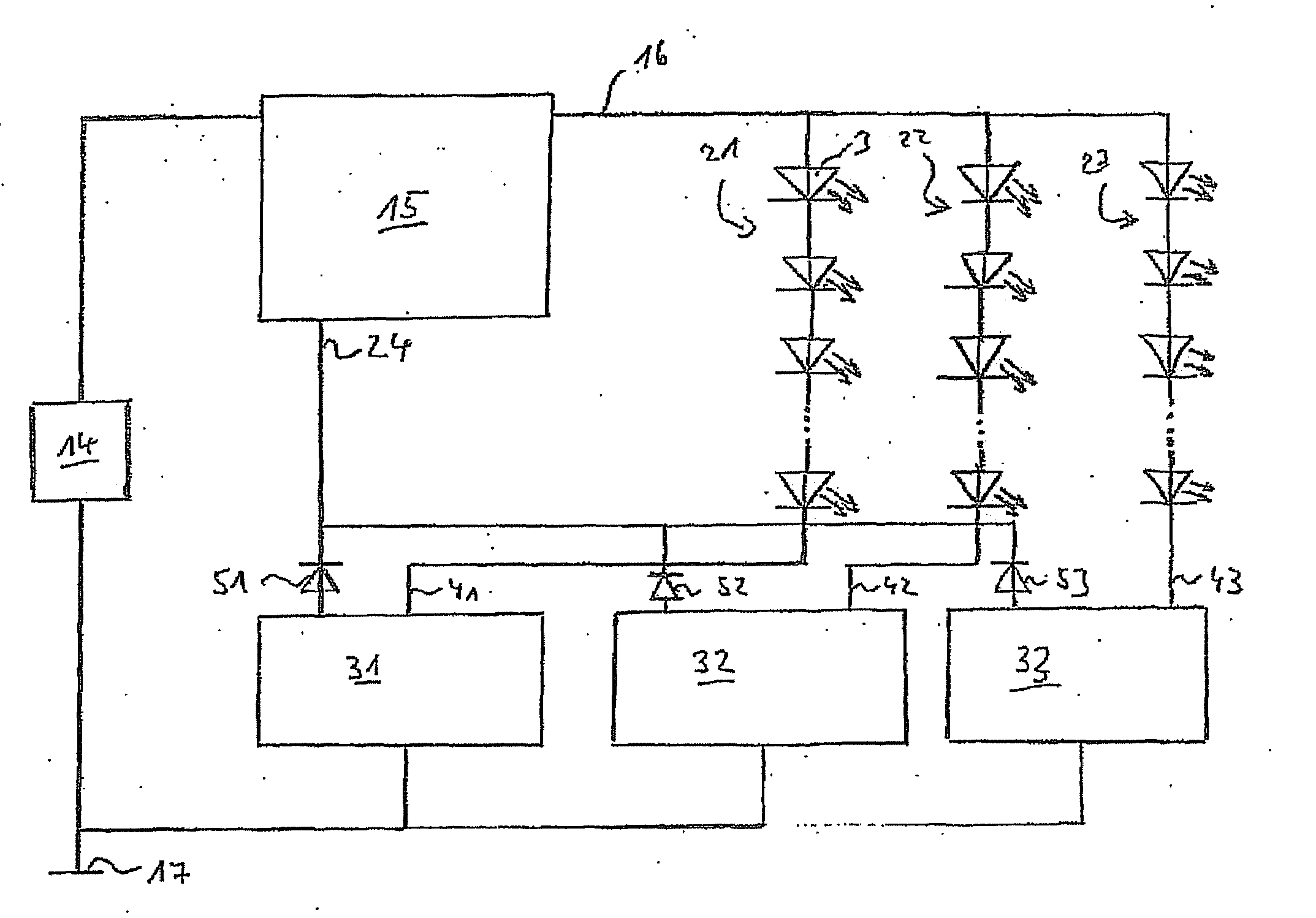
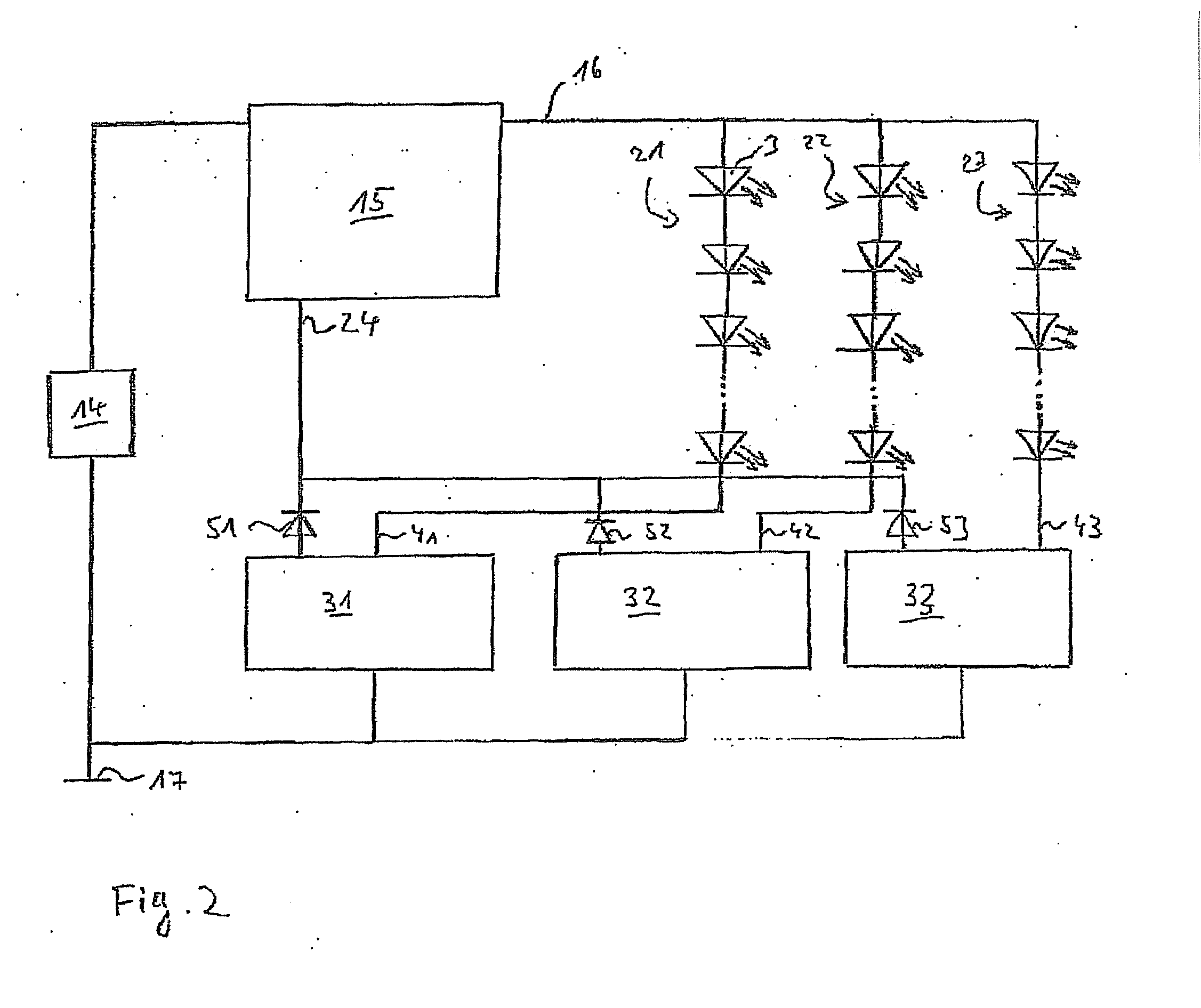
[0004]Besides these advantages which result when a series circuit of light-emitting diodes is connected to the drive device according to the example embodiment of the present invention, the following advantages are realized when multiple series circuits of light-emitting diodes are connected in parallel with the example drive device. Because of production-related tolerances, light-emitting diodes have slightly different characteristic curves, so that at a given applied voltage, different current flows result as a function of the characteristic curves of the light-emitting diodes used. For multiple series circuits of light-emitting diodes, under unfavorable conditions these errors may be additive, so that, for example, for two chains connected in parallel in an unfavorable manner one of the two chains does not illuminate, whereas the other chain is destroyed due to the excessively high current flow. By using a current regulation unit which according to the present invention is assigned to each of the series circuits, the current flow through the series circuits may be limited in each case, thereby preventing destruction of a series circuit of light-emitting diodes. At the same time, however, the
operating voltage may be increased until all light-emitting
diode chains connected to the drive device according to the present invention receive an operating voltage such that a current which is sufficient for light generation may be conducted through the light-emitting diodes. Thus, on the one hand, for multiple series circuits of light-emitting diodes connected in parallel to the drive device, all of the light-emitting diodes may be illuminated, whereas on the other hand, it is not possible for any of the series circuits to be destroyed as the result of excessively high current flow. By feeding a current regulation
signal from the current regulation unit to the
voltage regulation unit, this feedback may be used to link the current regulation with the
voltage regulation in an easily implemented manner to ensure that the necessary current is conducted through all the series circuits of light-emitting diodes. The series circuits of light-emitting diodes are operated at an intended
operating point as the result of the current being regulated to the required value. In this manner the optical parameters of the light-emitting diodes are stabilized. Furthermore, destruction of the light-emitting diodes is reliably avoided by suitably rapid regulation of the current. By regulating the supply voltage to exactly the required value, it is also possible to reduce power loss from the current regulation unit as well as from the
voltage generator.
[0006]It may be advantageous to feed the current regulation signals of all series circuits of the light-emitting diodes to one input of the
voltage regulation unit. In this manner, monitoring of only one input of the voltage regulation unit, taking into account the current regulation
signal associated with the series circuit of light-emitting diodes which requires the highest operating voltage, allows all series circuits to be easily illuminated by selecting the highest required operating voltage. On the other hand, the operating voltage need not be selected to be arbitrarily high, and instead may be adapted to the specific series circuit which requires the highest operating voltage. Multiple series circuits of light-emitting diodes may thus be reliably operated in an energy-conserving manner by using one drive device.
[0007]It may also be advantageous for the voltage regulation unit to have a step-up converter so that the operating voltage of the light-emitting diodes may be selected to be greater than a supply input voltage. It is thus possible to provide series circuits of light-emitting diodes which are so large that their operating voltage requirement is higher than a supply voltage which is available for operating the drive device.
[0010]It may also be particularly advantageous to use an example display unit according to the present invention in a motor vehicle, in which light-emitting diodes are used in particular for illuminating indicator displays and
liquid crystal displays, and sometimes are used in large numbers for units in the vehicle interior. Because of the low operating voltage, practically unlimited color selection, and low heating during operation, a light-emitting
diode may be used at various locations in the vehicle for reliable illumination.


