Apparatus for creating therapeutic charge transfer in tissue

a tissue and electrode technology, applied in the field of electric fields, can solve the problems of non-uniformity in intensity and geometry, invasive nature of electrodes, and threatening the beneficial effect, and achieve the effects of preventing excessive high voltage, large amount of energy, and high efficiency duty cycl

Inactive Publication Date: 2005-03-24
ADVATECH CORP
View PDF20 Cites 24 Cited by
  • Summary
  • Abstract
  • Description
  • Claims
  • Application Information

AI Technical Summary

Benefits of technology

FIG. 3B shows the effective circuit when the IGBT is not connected to ground and the energy stored in the coil is dissipated in the large resistance, Rp, and the short time reverse electric field is generated by the coil. It should be noted that this circuit is a closed loop and without any ground, although a capacitive connection to ground, called a “snubber” prevents excessively high voltages as the current is dissipated.
This dual circuit system allows the large currents that are required for effective therapy to flow into the treatment coil thereby storing large amounts of energy in the coil. This energy must then be very quickly dissipated to allow an immediate repetition of the cycle. The high-speed removal of the energy from the coil allows for both a high-energy electric treatment field and a high efficiency Duty Cycle. The exchange of energy between the coil and the resistance Rhd P produces a very large voltage spike in the circuit that can only be withstood by an IGBT or equivalent series of power transistors.

Problems solved by technology

The invasive nature of electrodes threatens the beneficial outcome of the clinical treatment and production of uniform electric fields within the treated tissue.
For example, the electrodes can cause infection or become displaced.
Moreover, the electric fields produced are non-uniform in both intensity and geometry due to the polarization of the surrounding media at each electrode with oppositely charged ions that weaken and distort the electric field.
The system disclosed could never produce a DC or rectified AC electric current in treated tissue.
Ivashina teaches to generate a field that is purely sinusoidal and as a result produces very limited charge transport.
In addition, Ivashina et al. do not teach or suggest incorporating specifically designed permanent or electromagnets that generate dynamic and stepwise changing magnetic fields to induce a continuous and uniform DC-like “square wave” electric field.
The issue as to the rejection as being anticipated by Abbott et al. is weather on not someone skilled in the art would be able to extend the inefficient application that Abbott et al. teaches by at least two orders of magnitude to the present teaching.
At these low frequencies, the lag time of current growth and decay would be very significant and the above assumptions fail.
Therefore, although Ryaby seems on first glance to be dealing with PEMP, the technology is not cable of inducting the therapeutic currents that are similar to a direct current supplied to tissue directly with electrodes.
Likewise, Abbott et al. is not capable of inducing sufficient electric fields with sufficient Duty Cycle to create the therapeutic effects that are similar when connecting a direct current directly to tissue using electrodes.
There is no prior art that teaches a method for achieving strong enough induced electric fields of sufficient duration (Duty Cycle) to produce the necessary quantity of charge transport in tissue of low conductivity.
Abbott et al. do not teach a magnetic field with sufficient Duty Cycle or strength to create therapeutic results.
Low energy electric signal wave trains of high frequency bursts, such as those taught by Abbott et al. with long intervals between bursts, produce low energy electric treatment fields with low efficiency Duty Cycles.
The methods used by the earlier teachings will not allow for the currents, voltages, or Duty Cycles that are necessary to produce sufficient electric charge transport as defined by Reich et al.
Any increase of such magnitude requires a significantly change in the overall design and circuits.
This technology and circuit design would never lead to an effective charge transport system in tissue.

Method used


Image

  • Apparatus for creating therapeutic charge transfer in tissue
  • Apparatus for creating therapeutic charge transfer in tissue
  • Apparatus for creating therapeutic charge transfer in tissue

Examples


Embodiment Construction

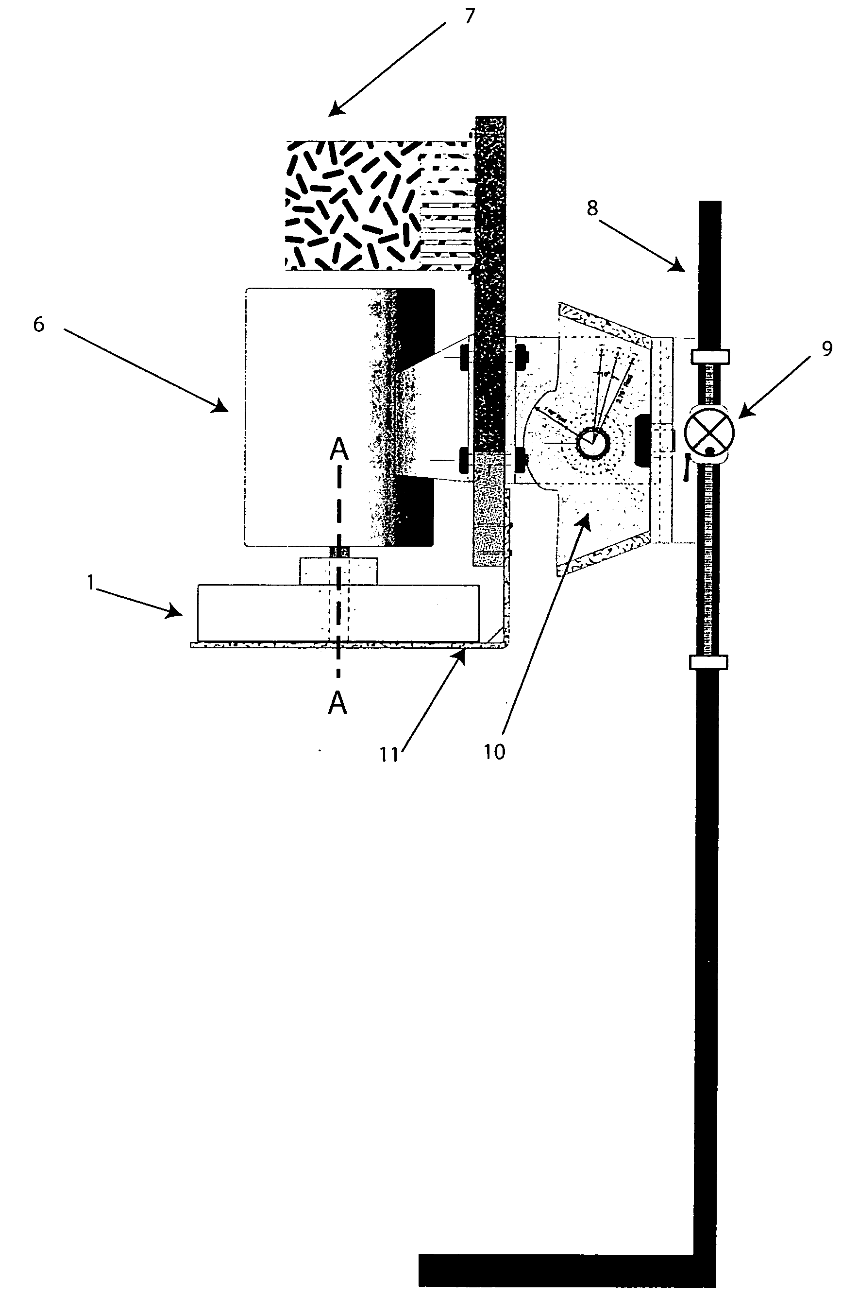
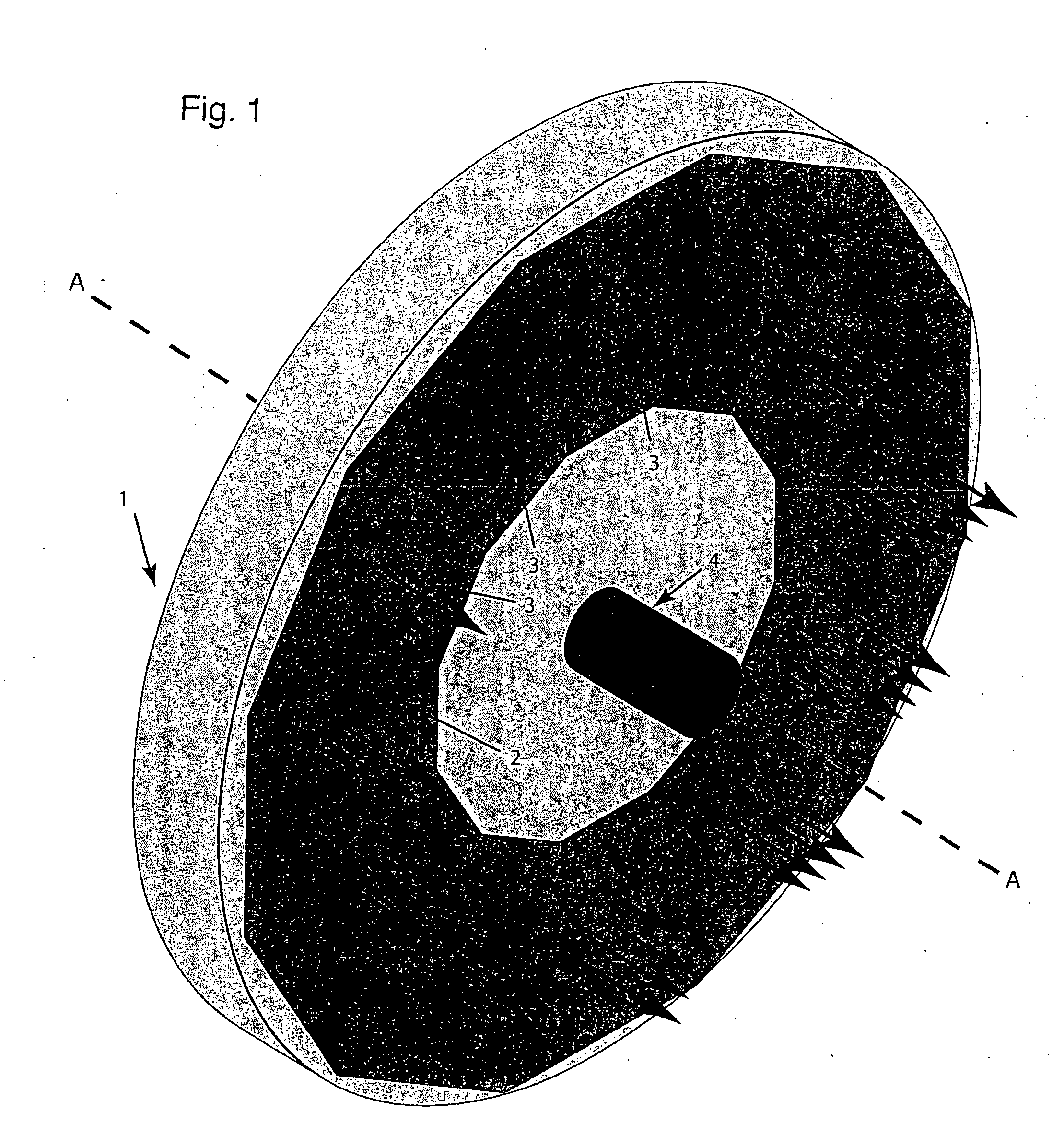
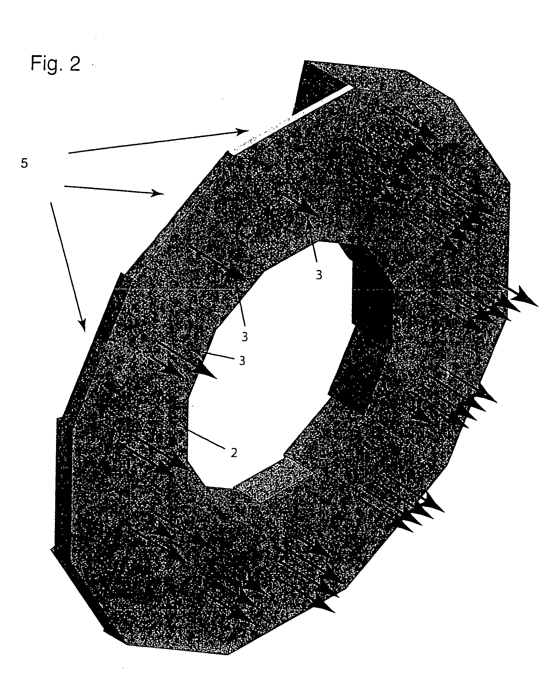
Reference will now be made in detail to the present preferred embodiments of the invention, examples of which are illustrated in the accompanying drawings. Wherever possible, the same reference numbers will be used throughout the drawings to refer to the same parts.

The present invention creates an induced DC-like electric field in biological material to treat the material. The biological material can be portions of a living human or animal, such as body fluids, cells, tissue, or bone.

The induced DC-like electric field can treat the biological material in numerous ways, including promoting regeneration of damaged tissue. For example, the DC-like electric field can treat trauma (e.g., bruises, torn muscles, and cartilage damage); debilitation; organs by stimulating their regeneration to restore their functions; damaged or severed human nerves or axons; slow or non healing bone fractures (nonunions); occlusion of blood flow due to formation of plaque or other forms of calcificatio...


PUM


Abstract

An apparatus for creating therapeutic charge transfer in tissue includes a coil. The coil generates a changing magnetic field to induct an electric field in the tissue exceeding 10 mV/cm when the coil is 5 cm from the tissue. Preferably, the magnetic field has a growth phase and a decay phase and a duration of the growth phase is at least ten times a duration of the decay phase. The apparatus can include a control circuit to control a current fed to the coil. The control circuit includes two subcircuits and a switch for switching between a first of the subcircuits and a second of the subcircuits; preferably, a λ of the second subcircuit is at least ten times a λ of the first subcircuit. To generate the therapeutic effect, the coil should have a duty cycle of at least ten percent.

Description

BACKGROUND OF THE INVENTION 1. Field of the Invention This invention relates to applying electric fields to various parts of the body for medical treatment. More specifically, this invention applies a changing magnetic field on human tissue, wherein the time change of magnetic field strength (dB / dt) produces a resultant electromotive force (EMF) on the ions in the tissue such as that caused by a direct electric current between two electrodes. Thus, the invention treats human tissues with time changing magnetic fields that induce an electric field. The invention also lies generally in the field of ion propulsion. More specifically, the invention relates to using a moving magnetic field such as those found in the area of plasma physics with certain applications concerned with rocket propulsion and controlled fusion. The application of this invention is not in these areas but is in a lower energy regime with application for the medicinal treatment of human bone, blood, tissue, and o...

Claims


Application Information

Patent Timeline
Patent Type & Authority Applications(United States)
IPC IPC(8): A61N2/02A61N2/04A61N2/12
CPCA61N2/12A61N2/02
Inventor SPIEGEL, MICHAEL
Owner ADVATECH CORP
Why Eureka
Try Eureka