
Drive device and method for operating at least one series circuit of light-emitting diodes

a technology of light-emitting diodes and drive devices, which is applied in the direction of electric variable regulation, process and machine control, instruments, etc., can solve the problems of not being able to destroy any of the series circuits, and operating points close to the minimum power loss, so as to achieve convenient operation, convenient implementation, and easy illumination

Inactive Publication Date: 2013-08-27
ROBERT BOSCH GMBH
View PDF15 Cites 24 Cited by
  • Summary
  • Abstract
  • Description
  • Claims
  • Application Information

AI Technical Summary

Benefits of technology

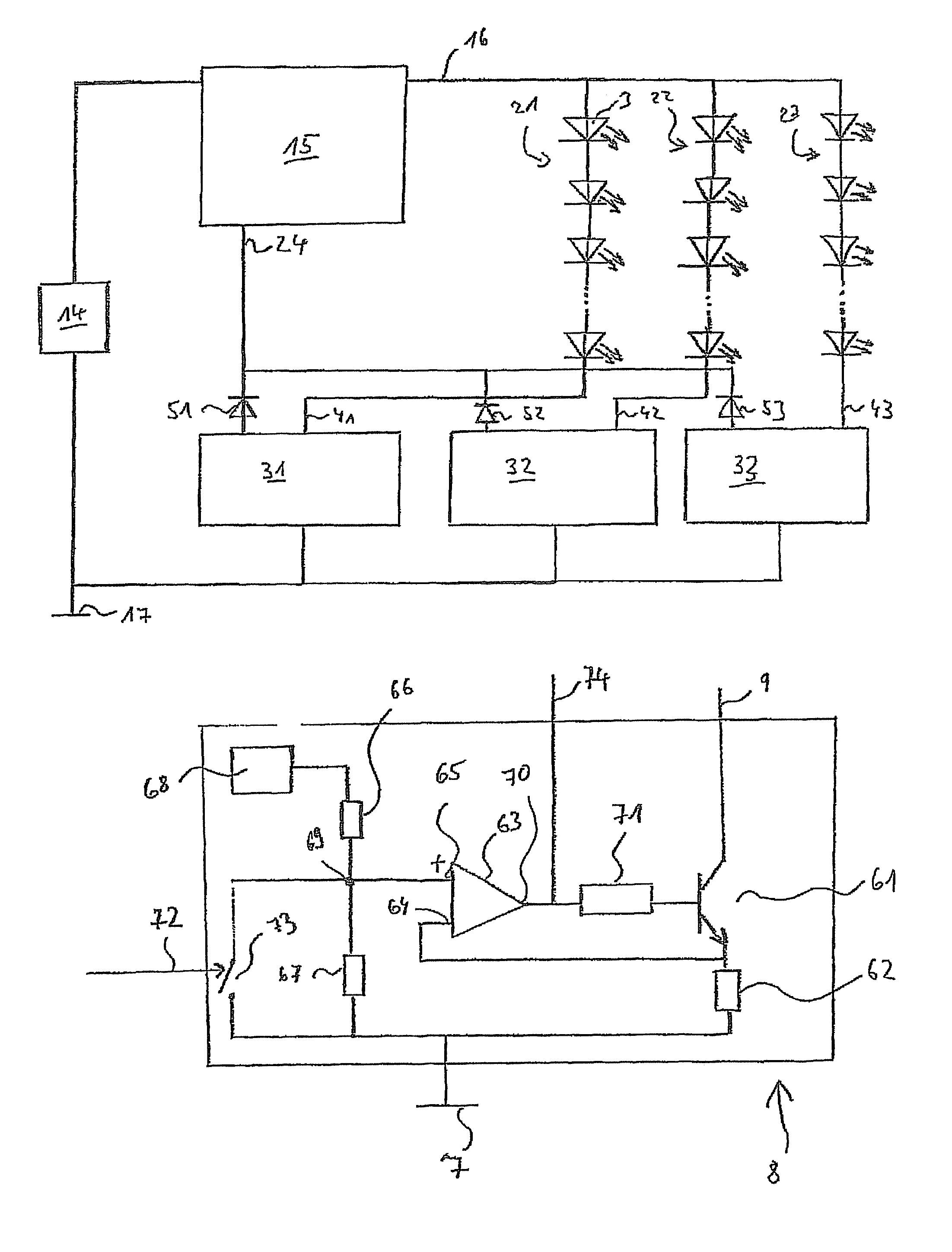
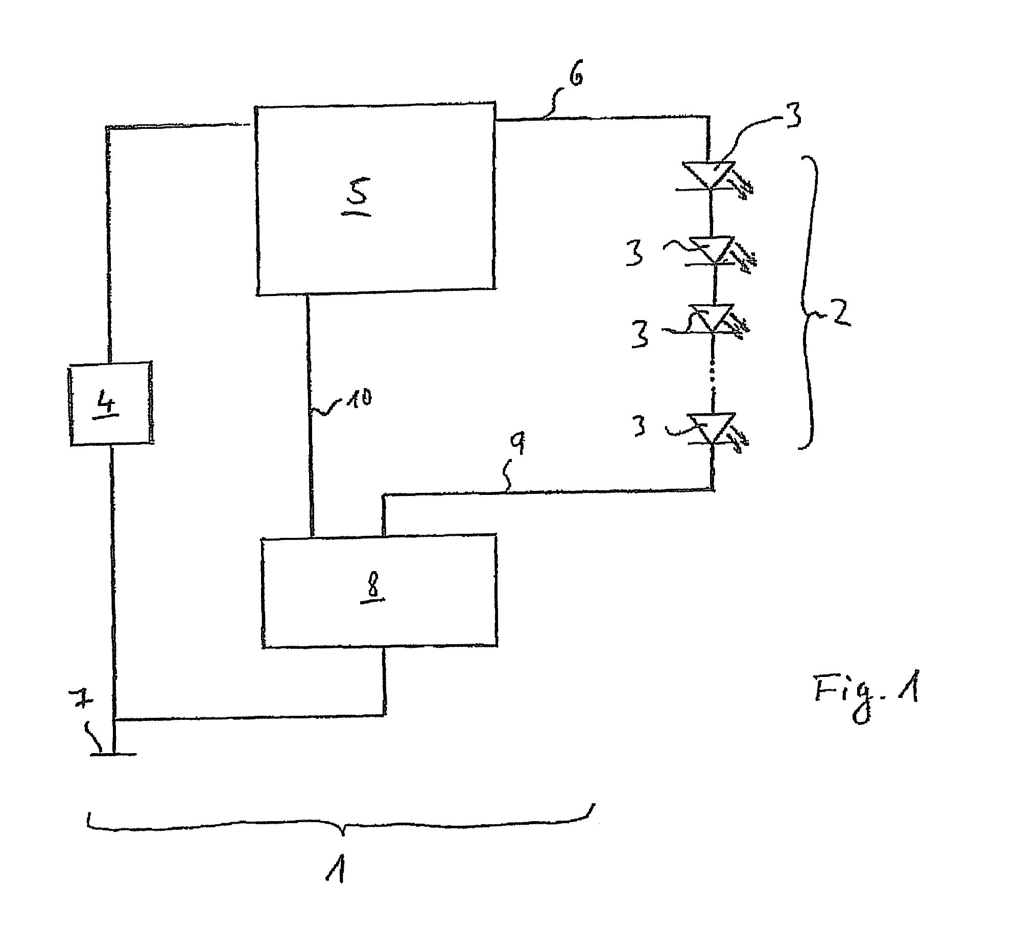
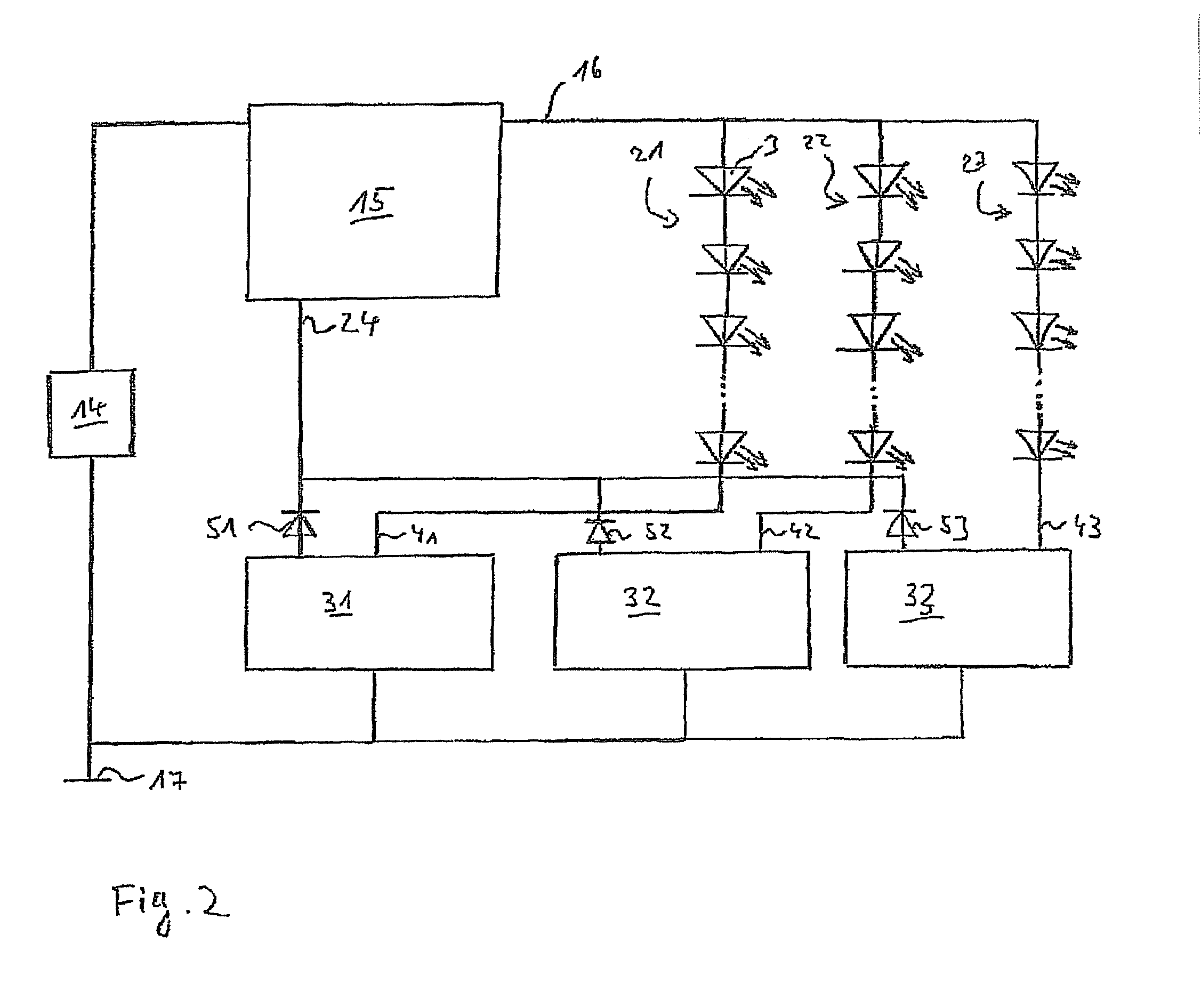
The present invention relates to a drive device for light-emitting diodes (LEDs) that achieves both high operational reliability and low power loss. The drive device regulates both the voltage and current flow through the LEDs, preventing damage due to excessive current flow and ensuring optimal power conversion. The use of multiple series circuits of LEDs in parallel with the drive device further prevents destruction of one circuit due to the others. The current regulation unit is easily integrated with the voltage regulation unit, simplifying the manufacturing process. The current regulation signals from all the series circuits are fed to one input of the voltage regulation unit, allowing for easy illumination of all circuits while conserving energy. The voltage regulation unit may have a step-up converter for higher operating voltage requirements of the LEDs. The use of LEDs in vehicles is advantageous due to their low operating voltage, practical unlimited color selection, and low heating during operation.

Problems solved by technology

This results in an operating point which is close to the minimum possible power loss.
For multiple series circuits of light-emitting diodes, under unfavorable conditions these errors may be additive, so that, for example, for two chains connected in parallel in an unfavorable manner one of the two chains does not illuminate, whereas the other chain is destroyed due to the excessively high current flow.
Thus, on the one hand, for multiple series circuits of light-emitting diodes connected in parallel to the drive device, all of the light-emitting diodes may be illuminated, whereas on the other hand, it is not possible for any of the series circuits to be destroyed as the result of excessively high current flow.

Method used


Image

  • Drive device and method for operating at least one series circuit of light-emitting diodes
  • Drive device and method for operating at least one series circuit of light-emitting diodes
  • Drive device and method for operating at least one series circuit of light-emitting diodes

Examples


Embodiment Construction

[0016]The example drive device according to the present invention for operating a series circuit of light-emitting diodes or multiple series circuits of light-emitting diodes in simultaneous parallel operation may be used for any given lighting purpose. Use in a vehicle is particularly advantageous, since the drive device according to the present invention allows both reliable and economical operation. In particular for the illumination of performance data in the vehicle, it is necessary that functioning of the drive device is continuously ensured so that a driver is able to read corresponding performance data. For this purpose the drive device according to the present invention may, for example, be introduced into a so-called combination instrument in front of the driver in which numerous display units, such as an indicator display or liquid crystal display, for example, are incorporated. Power is supplied via the vehicle electrical system, using a supply voltage between 10 V and 1...


PUM


Abstract

A device for at least one series circuit of multiple light-emitting diodes, having a voltage regulation unit for regulating an operating voltage for the at least one series circuit of the light-emitting diodes. A current regulation unit for regulating the current through the particular series circuit of light-emitting diodes is provided for each series circuit of light-emitting diodes, and the current regulation unit is connected to the voltage regulation unit in order to transmit a current regulation signal to the voltage regulation unit.

Description

FIELD OF THE INVENTION[0001]The present invention is directed to a drive device and method.BACKGROUND INFORMATION[0002]A drive circuit is described in German Patent Application No. DE 198 41 270 A1 for generating a constant current through at least one light-emitting diode. The drive circuit contains a circuit system for generating a voltage which differs from a specified supply voltage and which is applied to the light-emitting diodes to be operated. A current flowing through the light-emitting diodes is detected by a current detector. The voltage present at the output of the circuit system is selected as a function of the magnitude of the current flowing through the light-emitting diodes.SUMMARY[0003]An example drive device according to the present invention may have the advantage that on the one hand a high degree of operational reliability is achieved, and on the other hand power loss is minimized. These advantages may be achieved due to the fact that not only the operating volt...

Claims


Application Information

Patent Timeline
Patent Type & Authority Patents(United States)
IPC IPC(8): H05B37/02H05B44/00
CPCH05B33/0815H05B33/0827H05B33/0851Y02B20/347H02M3/156H05B45/46H05B45/10Y02B20/30H05B45/38H02M1/0025
Inventor KRESPACH, ANDREASWENK, STEPHAN
Owner ROBERT BOSCH GMBH
Learn More