
Method for optimizing an unrouted design to reduce the probability of timing problems due to coupling and long wire routes

a technology of unrouted design and optimization method, which is applied in the direction of cad circuit design, program control, instruments, etc., can solve the problems of difficult and expensive incremental update of the impact of certain effects, electrical violations, failure of signals to meet timing, etc., and achieve the effect of decreasing the totaldeltadelay and increasing the slack

Inactive Publication Date: 2011-02-22
GLOBALFOUNDRIES INC
View PDF3 Cites 13 Cited by
  • Summary
  • Abstract
  • Description
  • Claims
  • Application Information

AI Technical Summary

Benefits of technology

The present invention is about predicting the effects of coupling on timing in an integrated circuit design. It estimates the delay and slack that can occur due to coupling between nets, and optimizes the design to minimize the impact of slack on potential coupling violations. It also predicts slacks that may show up after detail routing and coupling analysis, and enables earlier correction of potential timing problems to reduce the need for post-routing repairs. The invention does not require duplication of the delay graphs and can anticipate likely effects of coupling in early optimization. Overall, the invention improves the accuracy and efficiency of integrated circuit design.

Problems solved by technology

Coupling is the cause of both timing violations (failure of signals to meet timing requirements) and electrical violations (e.g., excessive signal slew and transition time or excessive effective load capacitance on a driver).
Even when routing information is available, it is difficult and expensive to incrementally update the impact of certain effects, like coupling on the timing results.
However, these methods still cannot operate until routing has been performed.
Coupling plays a major role in causing a large number of post-routing timing violations.
While Steiner estimates are generally close to the final routing results, on occasion, the actual routes can be significantly longer than predicted, e.g., due to the need to route around blockages or congestion.
The increased effective capacitance of a net due to coupling or long wire routes not only affects the delay of that net and its driver, but also increases or degrades the slew (the time the signal takes to make a transition) at the gate output and net sink.
Three approaches exist to predict timing effects of long wires or coupling early in the design process:1. One can assume coupling / long wire routes for all the nets in the design, but this is highly pessimistic and can lead to considerable over-design and / or difficulty in closing timing.2. One can include some built-in pessimism in the electrical parasitic extraction parameters used with estimated Steiner routes to take into account potential coupling capacitance or long wire routes that cannot be known until later in the design process.
It also fails to account for the delay impacts of propagated slew degradation due to a coupling event or a long wire route.3. The fault-tolerant static timing analysis approach described in U.S. Pat. No. 6,795,951 can capture the local impact of a predetermined number of coupling events and / or long wire routes along any path, but is expensive due to duplication of the timing graph.

Method used


Image

  • Method for optimizing an unrouted design to reduce the probability of timing problems due to coupling and long wire routes
  • Method for optimizing an unrouted design to reduce the probability of timing problems due to coupling and long wire routes
  • Method for optimizing an unrouted design to reduce the probability of timing problems due to coupling and long wire routes

Examples


Embodiment Construction

n the principles of the invention

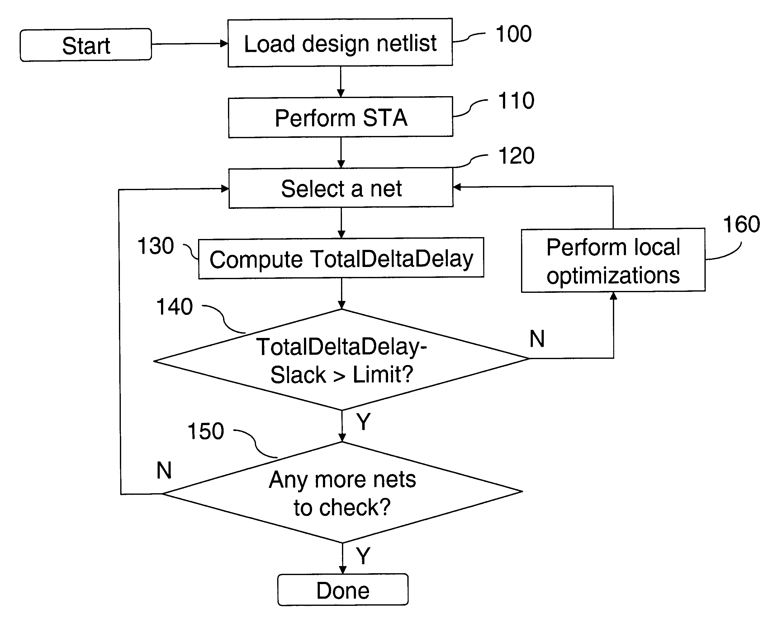
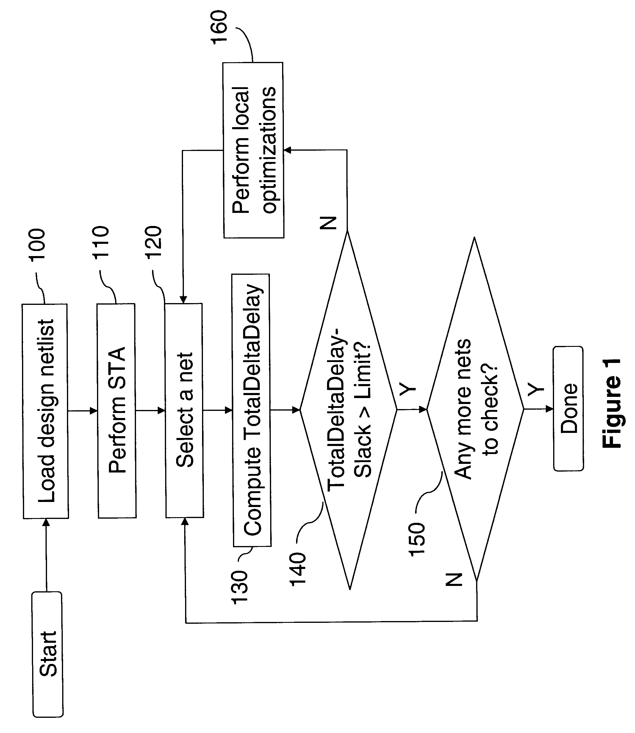
[0021]FIG. 1 is a flowchart illustrating a timing closure process embodying the inventive method.

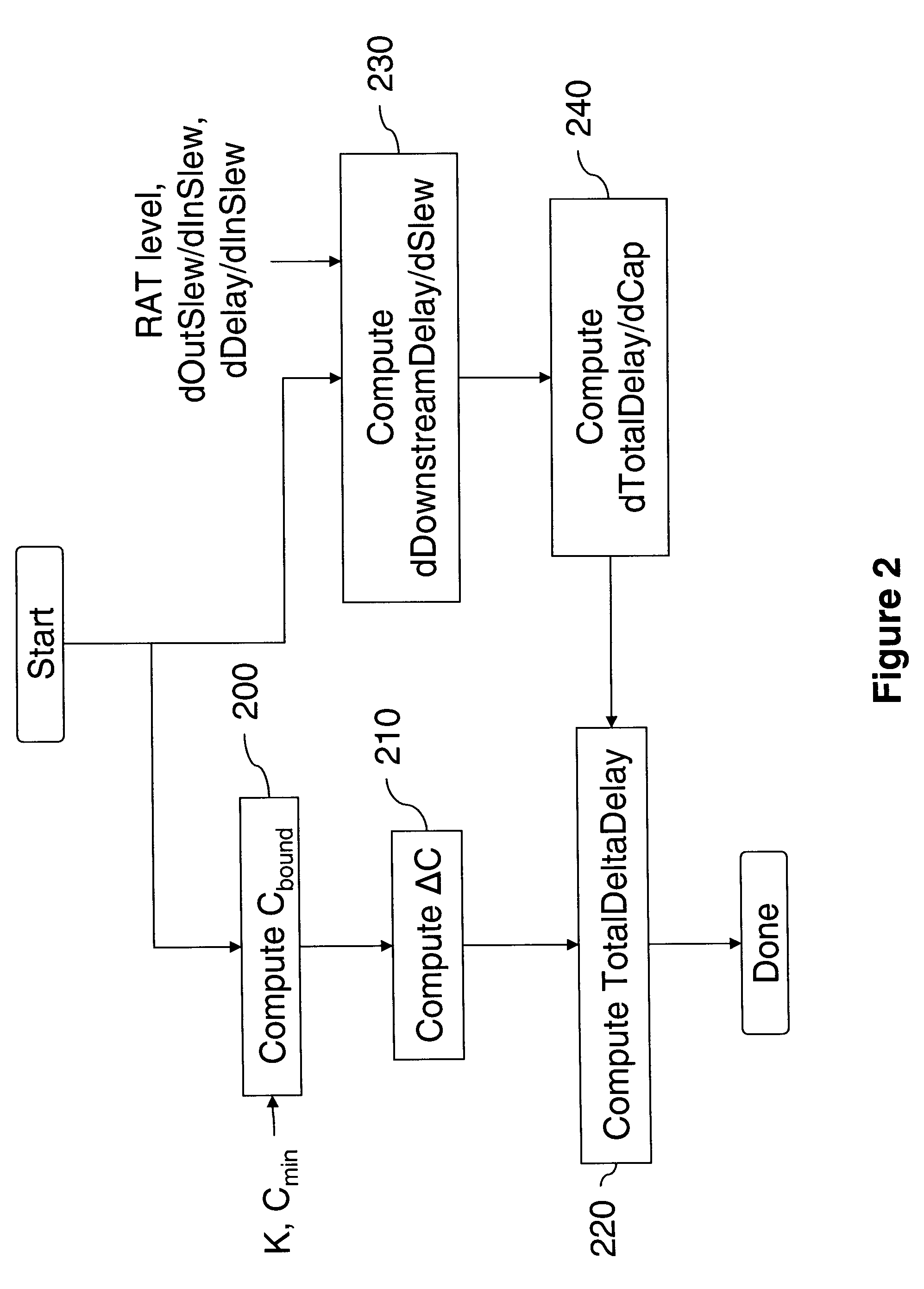
[0022]FIG. 2 is a flowchart illustrating the computation of a TotalDeltaDelay value for a net.

[0023]FIG. 3 is a plot of Cactual versus Cestimate for a collection of nets.

[0024]FIG. 4 is a flowchart illustrating the computation of K and Cmin values used to compute Cbound.

[0025]FIG. 5 is an exemplary circuit to which the inventive method is applied.

DETAILED DESCRIPTION OF PREFERRED EMBODIMENTS

[0026]The present invention and the various features and advantageous details thereof are explained more fully with reference to the non-limiting embodiments that are illustrated in the accompanying drawings and detailed in the following description.

[0027]The present inventive method computes before routing a change in delay, hereinafter referred to as TotalDeltaDelay that could reasonably be expected to occur due to coupling, long wire routes, or other characteristics...


PUM


Abstract

A method and a system is described to predict effects of coupling on timing by estimating the delta delay and delta slack that can occur due to coupling on any net, for optimization to minimize the sensitivity of slack to potential coupling violations. The invention protects against other unexpected increases in effective load capacitance, such as those due to unexpectedly long wire routes. It also estimates the delay impact of a single ‘fault’ or ‘event’, such as a coupling event or unexpectedly long wires routes, including the impact of slew propagation.

Description

FIELD OF THE INVENTION[0001]The present invention generally relates to very large scale integrated (VLSI) circuit designs, and more particularly, to a system and method for setting up a timing environment for use during early optimization stages to capture timing effects caused by long wires routes and coupling.BACKGROUND OF THE INVENTION[0002]Timing optimization of a logic network is typically performed using an integrated incremental timing analyzer, and is invoked at different stages of the design process, e.g., before placement, and after placement and routing. A benefit of this approach is that the design changes that are required to correct large problems can be made before subsequent expensive design stages such as placement and routing, reducing the computational expense that would otherwise be required to incrementally update the design decisions made during these subsequent processes.[0003]Coupling between nets can affect the timing of a logic network, and its impact on th...

Claims


Application Information

Patent Timeline
Patent Type & Authority Patents(United States)
IPC IPC(8): G06F17/50
CPCG06F17/5031G06F17/5045G06F30/3312G06F30/30G06F30/3315G06F2119/12
Inventor KOTECHA, POOJA M.HATHAWAY, DAVID J.TREVILLYAN, LOUISE H.
Owner GLOBALFOUNDRIES INC
Learn More