Weapon mount

a technology of a weapon and a mount, applied in the field of weapons, can solve the problems of robot arms that are often susceptible to damage, the recoil mitigation system may not adequately arrest the weapon, and the robot or its components may be damaged, so as to prevent damage to the effect of preventing the damage of the robot and/or the robot or the weapon, and preventing the damage of the robot and/or the weapon components

Active Publication Date: 2011-03-01
FOSTER-MILLER
View PDF31 Cites 15 Cited by
  • Summary
  • Abstract
  • Description
  • Claims
  • Application Information

AI Technical Summary

Benefits of technology

It is a further object of this invention to provide such a weapon mount which adequately mitigates recoil of the weapon.
It is a further object of this invention to provide such a weapon mount which prevents damage to the robot and / or components of the robot or weapon.
It is a further object of this invention to provide such a weapon mount which does not adversely affect the performance of the weapon.
It is a further object of this invention to provide such a weapon mount in which the amount of braking force is readily adjustable and can be repeatably set to pre-determined values.

Problems solved by technology

But, the robot arm is often susceptible to damage caused by the shock force produced by the recoil of the disruptor when fired.
With some munitions, such a recoil mitigation system may not adequately arrest the weapon.
Or, the robot or its components may be damaged if too much frictional force is applied.
The amount of friction, however, was not readily adjustable, was not repeatable due to wear and / or intolerances, and the set value of the frictional force was difficult to determine by the user.
Breech vent recoil mitigation techniques may rob the weapon of performance and reduce the muzzle velocity of the projectile used.
Various shock absorber techniques proved to be costly, heavy, and difficult to implement due to the preference to accommodate a long stroke of the disruptor barrel.

Method used


Image

  • Weapon mount
  • Weapon mount
  • Weapon mount

Examples


Embodiment Construction

Aside from the preferred embodiment or embodiments disclosed below, this invention is capable of other embodiments and of being practiced or being carried out in various ways. Thus, it is to be understood that the invention is not limited in its application to the details of construction and the arrangements of components set forth in the following description or illustrated in the drawings. If only one embodiment is described herein, the claims hereof are not to be limited to that embodiment. Moreover, the claims hereof are not to be read restrictively unless there is clear and convincing evidence manifesting a certain exclusion, restriction, or disclaimer.

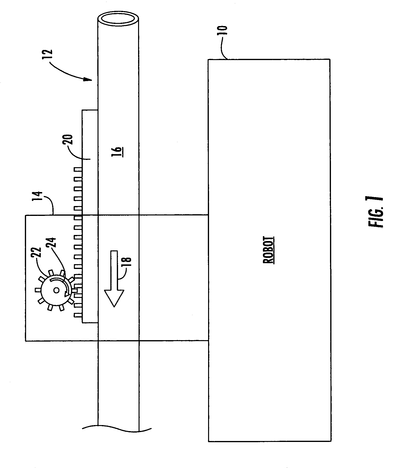
FIG. 1 schematically shows robot 10 (e.g., a remotely controlled mobile “Talon” robot (Foster-Miller, Inc., Waltham, Mass.) with weapon 12 mounted thereto, for example a disruptor. Other robot platforms are possible in accordance with the subject invention. See, for example, U.S. Pat. Nos. 4,621,562; 6,113,343; and U.S. Patent Pu...


PUM


Abstract

A mobile remotely controlled robot includes a robot platform and a robot arm maneuverable with respect to the robot platform. A housing is configured to be removably mounted to the robot arm. A sleeve is translatable with respect to the housing for receiving a weapon therein. There is a gear rack on the sleeve and a pinion gear, rotatably disposed in the housing, is engaged with the gear rack. A braking subsystem resists rotation of the pinion gear when the gear rack translates upon firing of the weapon.

Description

FIELD OF THE INVENTIONThis subject invention relates to weapons, in one example a disrupter; to mobile remotely controlled robots; and to weapon mounts.BACKGROUND OF THE INVENTIONDisruptors are used to disarm or render inoperable an explosive. Typically, the disruptors are fired from a remote location. Personnel typically set up a stand near an explosive device and attach the disruptor to the stand so it is aimed at the explosive. The disruptor is then fired from a remote, safe location.It is also known to equip a mobile remotely controlled robot with a disruptor. That way, personnel need not ever position themselves too close to the explosive device. Typically, the disruptor is mounted to a manipulatable arm of the robot so the disruptor can be correctly aimed and positioned. But, the robot arm is often susceptible to damage caused by the shock force produced by the recoil of the disruptor when fired.Various recoil mitigation techniques have been tried. U.S. Pat. Nos. 6,889,594; 6,...

Claims


Application Information

Patent Timeline
Patent Type & Authority Patents(United States)
IPC IPC(8): B64D1/04
CPCF41A25/08
Inventor FISK, ALLAN T.HUG, HANSJOHNSON, MICHAEL T.DESMEULE, NATHAN R.
Owner FOSTER-MILLER
Why Eureka
Try Eureka