Hydraulically operated protector for downhole devices

a technology of protectors and downholes, applied in the direction of drilling casings, well accessories, drilling pipes, etc., can solve the problems of reducing the service life of tools, and creating holes through which cement slurry will escape, so as to prevent fluid circulation and re-establish fluid circulation.

Inactive Publication Date: 2011-03-01
SCHLUMBERGER TECH CORP
View PDF5 Cites 3 Cited by
  • Summary
  • Abstract
  • Description
  • Claims
  • Application Information

AI Technical Summary

Benefits of technology

[0006]In a first aspect, the present invention proposes a protecting assembly consisting of a service tool including a tubular sheath for covering at least part of the device, for instance while the device is transferred from the surface down the hole. Abutting the upper extremity and disposed in the tubular sheath is a piston assembly that comprises a hydraulic piston with a tubular body and a dynamic seat translating along the tubular body. The hydraulic piston displaces the device between an upper position inside (or at least partly inside) the sheath and an active position outside the sheath. Means is also provided for preventing fluid circulation towards the device when the piston displaced it—and for reestablishing fluid circulation after extraction of the device out of the sheath.
[0012]According to a preferred embodiment, the protecting device of the invention further includes locking means for preventing an accidental displacement of the dynamic seat, for instance to make the relative translation of the dynamic seat only possible once the piston has extracted the device out of the sheath.
[0014]The protecting service tool of the invention provides multiple benefits. The device is perfectly protected during surface transportation and installation. The system is fully operated by hydraulic pressure: no movement is required in the running string, which is especially suitable for horizontal or deviated wells. The actuation of the system can be controlled from the surface by using a single ball or dart, which greatly simplifies the operation (no volume calculation between darts, no need for a dart launcher, pumping is continuous . . . ).
[0015]The automatic sequence of events simplifies the operation and it eliminates the risk of human error. Moreover, the operation can be monitored from the surface by observing a specific pressure signature. The extraction of the device can be achieved at any pressure, as the device is not exposed to that pressure. The device is not exposed to any differential pressure before it is entirely pulled out of the protector. This is important because a prematurely actuation could prevent the correct extraction out of the protector and / or damage the device. Thus the system is compatible with hydraulic devices such as a bag made of woven material, an inflatable rubber element, or an articulated arm operated by pressure.

Problems solved by technology

In cased wells, tool wearing by the casing is typically limited.
However, in uncased wells, the borehole walls constitute highly abrasive surfaces that tend to damage the tools, in particular elements that are in contact with the borehole walls when running the tools that are typically folded away during placement operations and / or elements that are deflated such as packer, often made of rubber or other readily abraded materials.
This raised issues in particular with the development of horizontal or highly deviated wells where the tools may be literally dragged along the borehole.
Since the mesh is necessarily loose to allow deformation, threads can easily get loose, thereby creating holes through which the cement slurry will escape.

Method used


Image

  • Hydraulically operated protector for downhole devices
  • Hydraulically operated protector for downhole devices
  • Hydraulically operated protector for downhole devices

Examples


Embodiment Construction

[0024]The same references will be used to reference the same elements in the Figures throughout the description.

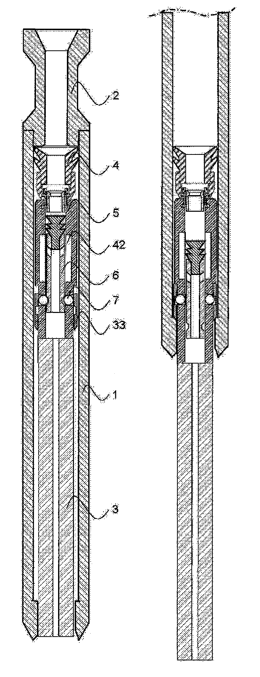
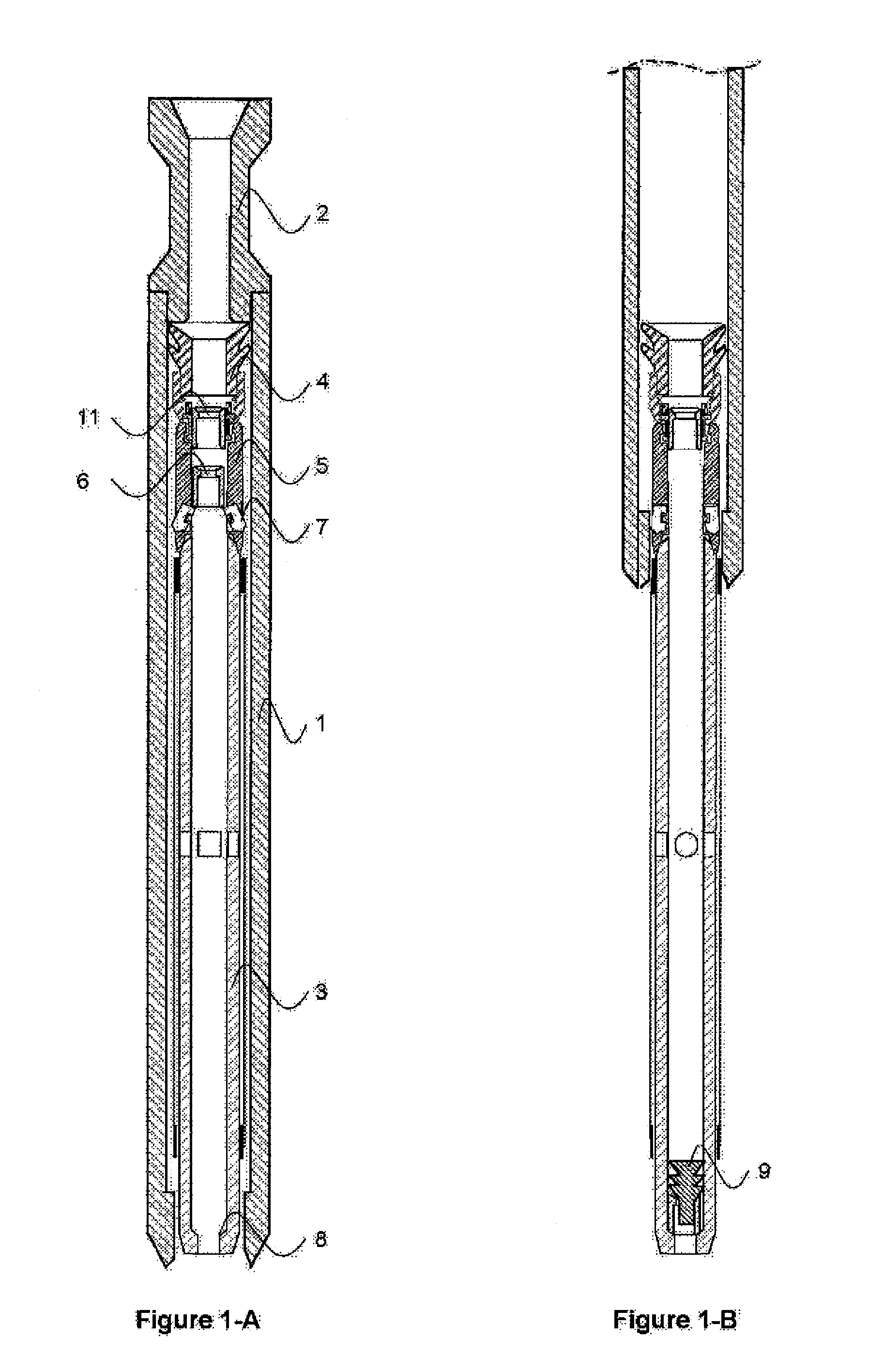
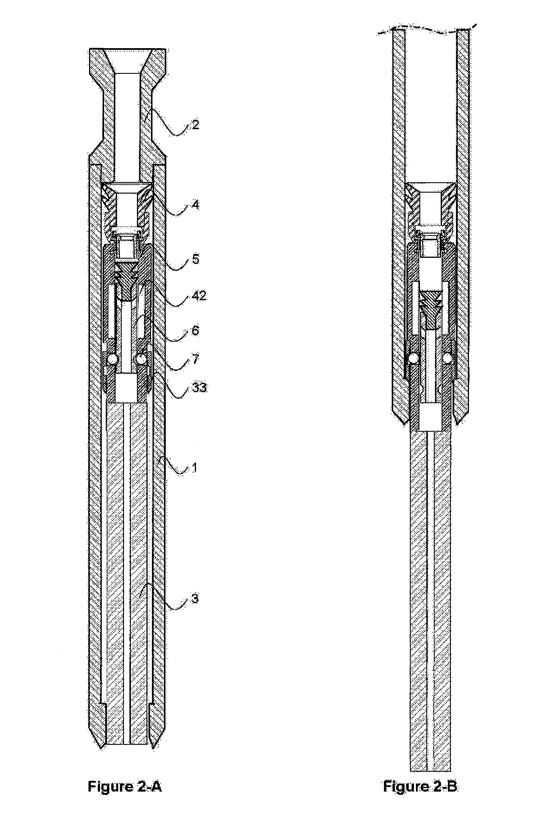
[0025]FIG. 1 is an illustration of a first embodiment of the present invention where the dynamic seat moves all along the protected device. As shown FIG. 1A, a tubular protective sheath 1 is secured, for instance through threading, at the bottom 2 of tubing, drill pipes, jointed pipes, coil tubing or other string of pipe known in the art. The dimensions of this sheath 1 are adjusted to entirely protect the device against shocks during transportation. Installation though sheaths ensuring only partial coverage may also be used in some cases. The sheath 1 is typically made of a strong material such as steel, for instance as a casing joint.

[0026]A hydraulically operated device 3 is stored inside the sheath. In this illustrated case, the protective sheath 1 extends all along the tool but it goes without saying that the invention may also be carried out with a protecting sheath ...


PUM


Abstract

A tool and its operating procedure are provided to protect any device while lowering into a well, and especially hydraulic devices such as sensors with expandable arms or inflatable elements such as packers. The protection is mainly important in the open hole of highly deviated or horizontal wells, for any device equipped with external seal element, delicate sensor or articulated parts. This tool features an automatic sequence controlled by a single dart or a single ball launched into the running string from the surface: when the dart or the ball lands on its seat, the pressure build-up is initially applied to a piston to extract the device from the protector without exposing it to any differential pressure, then it is automatically applied to the device itself for actuation as soon as the device is entirely pulled out of the protector.

Description

FIELD OF THE INVENTION[0001]The present invention relates to the field of downhole tools. More particularly the invention relates to servicing apparatus for completing downhole wells such as hydrocarbon wells.BACKGROUND ART[0002]In the art of well drilling, it is common practice to run multiple tools, often using conventional setting mechanisms. In cased wells, tool wearing by the casing is typically limited. However, in uncased wells, the borehole walls constitute highly abrasive surfaces that tend to damage the tools, in particular elements that are in contact with the borehole walls when running the tools that are typically folded away during placement operations and / or elements that are deflated such as packer, often made of rubber or other readily abraded materials.[0003]Some types of cover sometimes protect the most sensitive parts of the tools but overall, the tools are left exposed to the aggressive wellbore environment, for example as in U.S. Pat. No. 6,315,041. This raised...

Claims


Application Information

Patent Timeline
Patent Type & Authority Patents(United States)
IPC IPC(8): E21B23/04
CPCE21B17/076E21B17/1085E21B23/04E21B23/042
Inventor RAYSSIGUIER, CHRISTOPHEBEDEL, JEAN-PHILIPPE
Owner SCHLUMBERGER TECH CORP
Why Eureka
Try Eureka