Angular velocity detection apparatus
a detection apparatus and angular velocity technology, applied in the direction of generators/motors, turn-sensitive devices, instruments, etc., can solve the problem of large error in detection results, and achieve the effect of high accuracy
- Summary
- Abstract
- Description
- Claims
- Application Information
AI Technical Summary
Benefits of technology
Problems solved by technology
Method used
Image

Examples
first embodiment
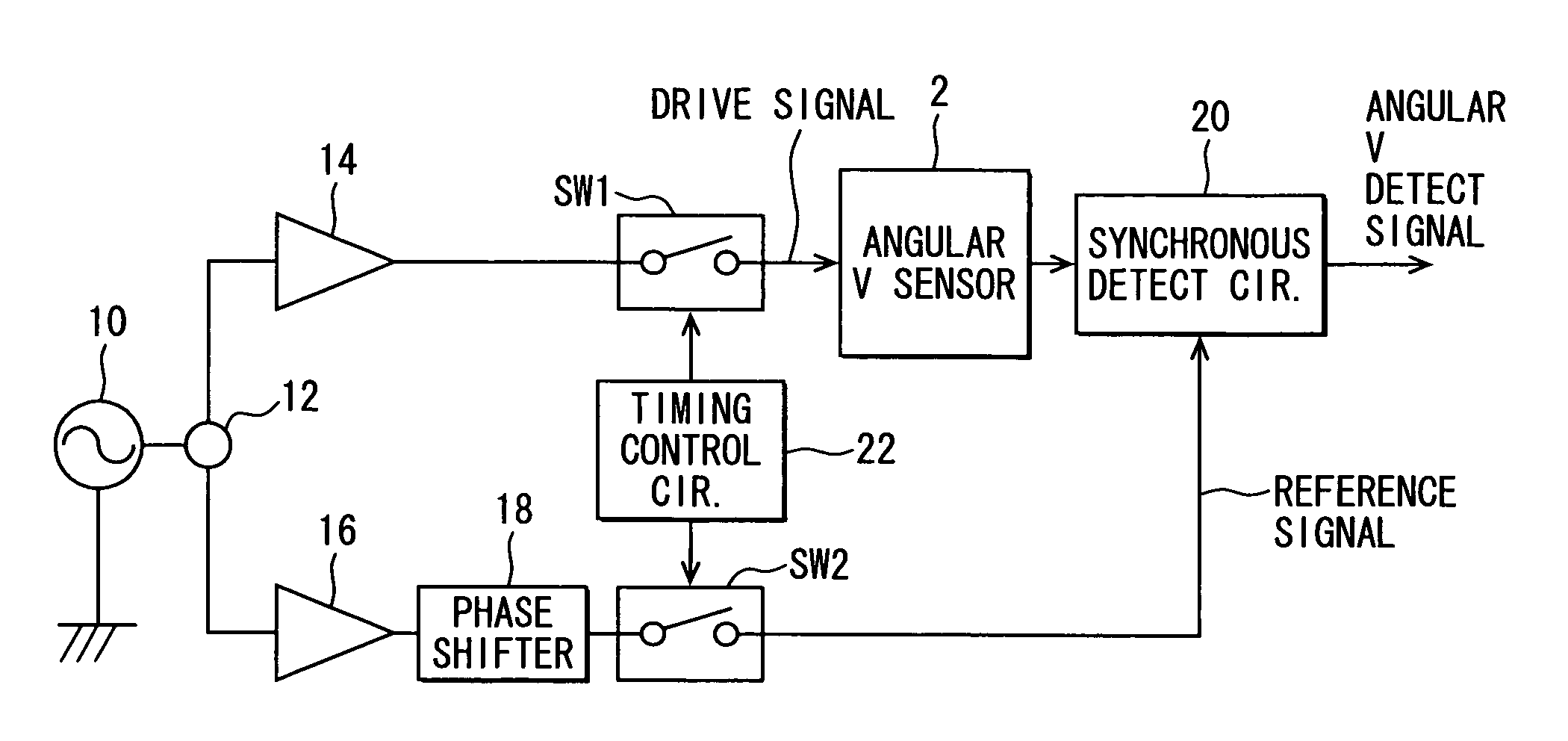
[0035]FIG. 1 is a block diagram illustrating an angular velocity detection apparatus in accordance with a first embodiment.
[0036]As shown in FIG. 1, the angular velocity detection apparatus of the present embodiment includes a surface acoustic wave (SAW) angular velocity sensor 2, an oscillator 10, a divider 12, a first amplifier circuit 14, a second amplifier circuit 16, a phase shifter 18, and a synchronous detection circuit 20. The surface acoustic wave angular velocity sensor 2, which is simply referred to hereinafter as an augural velocity sensor, may have a configuration generally similar to that shown in FIG. 6. The oscillator 10 generates a high-frequency signal used as a basis for forming a driving signal and a reference signal. The divider 12 divides the signal outputted from the oscillator 10 into two signals, which are called a first divided signal and a second divided signal. The first amplifier circuit 14 amplifies the first divided signal to a first predetermined leve...
second embodiment
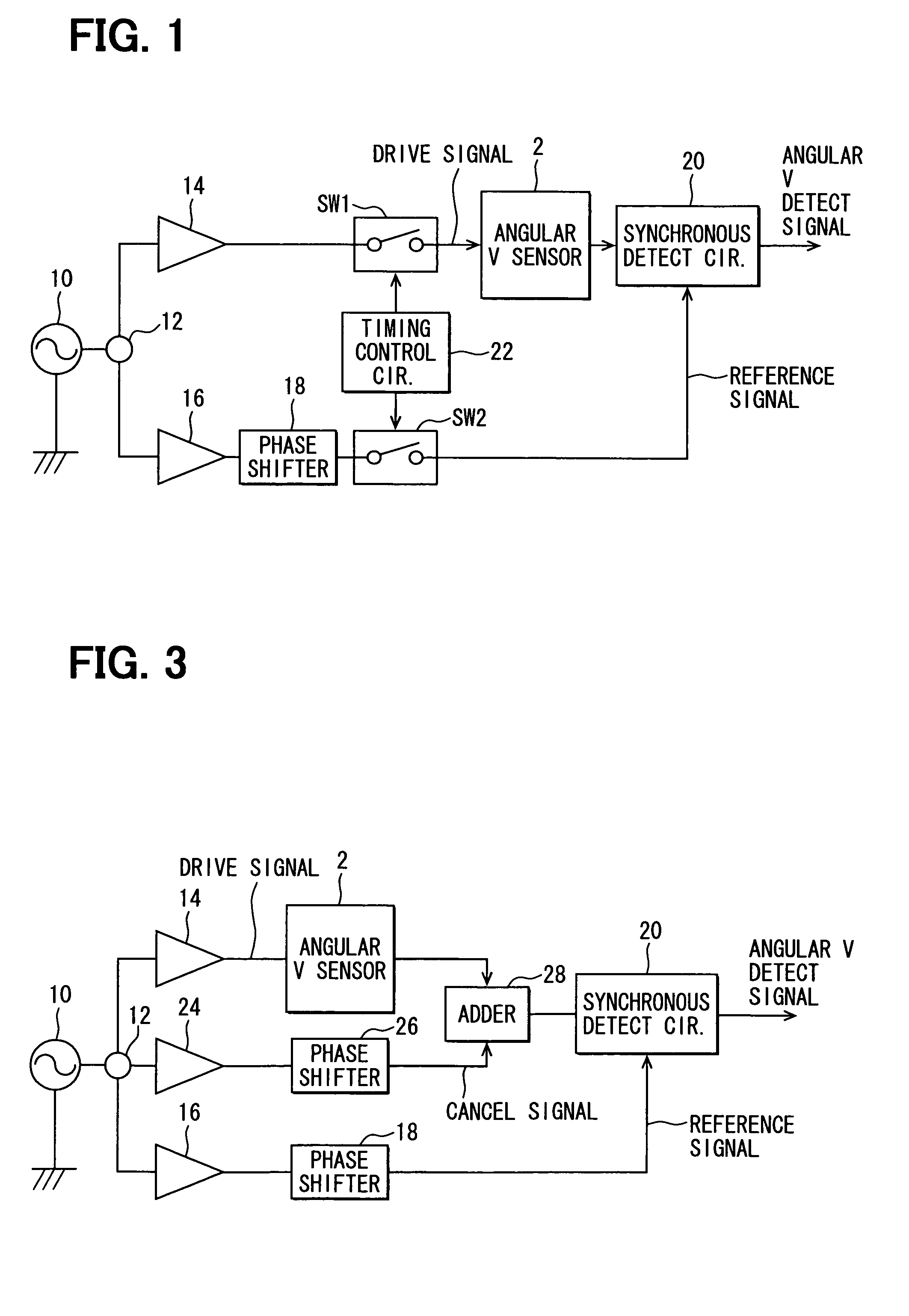
[0045]FIG. 3 is a block diagram illustrating an angular velocity detection apparatus in accordance with a second embodiment.
[0046]As shown in FIG. 3, the angular velocity detection apparatus of the present embodiment includes an angular velocity sensor 2, an oscillator 10, a divider 12, a first amplifier circuit 14, a second amplifier circuit 16, a third amplifier circuit 24, phase shifter 18, 26, a synchronous detection circuit 20, and an adder circuit 28 The first amplifier circuit 14 is used for generating a driving signal. The sensing electrode 8 and the phase shifter 18 are used for generating a reference signal.
[0047]The divider 12 divides a signal outputted from the oscillator 10 into three signals for three lines. The three divided signals are respectively outputted to the first, second and third amplifier circuits 14, 16 and 24.
[0048]The third amplifier circuit 24 is used to create a signal (i.e., cancel signal) for canceling a signal component representative of an unwanted...
third embodiment
[0054]FIG. 4 is a block diagram illustrating an angular velocity detection apparatus in accordance with a third embodiment.
[0055]As shown in FIG. 4, the angular velocity detection apparatus of the present embodiment, compared to that of the second embodiment, further includes an amplitude detection circuit 32, a phase detection circuit 34, and a gain phase-shift adjustment circuit 30.
[0056]The amplitude detection circuit 32 detects amplitude of the output signal from the sensing electrode 8 of the angular velocity sensor 2. The phase detection circuit 34 detects a phase of the output signal from the sensing electrode 8 of the angular velocity sensor 2.
[0057]The gain phase-shift adjustment circuit 30 detects the output signal from the angular velocity sensor 2, i.e., detects the unwanted wave signal component when the angular velocity sensor 2 is not subjected to angular velocity. Based on a detection result of the output signal, the gain phase-shift adjustment circuit 30 automatical...
PUM
 Abstract
Description
Claims
Application Information
 - R&D
- Intellectual Property
- Life Sciences
- Materials
- Tech Scout
- Unparalleled Data Quality
- Higher Quality Content
- 60% Fewer Hallucinations
Browse by: Latest US Patents, China's latest patents, Technical Efficacy Thesaurus, Application Domain, Technology Topic, Popular Technical Reports.
© 2025 PatSnap. All rights reserved.Legal|Privacy policy|Modern Slavery Act Transparency Statement|Sitemap|About US| Contact US: help@patsnap.com