
Systems and methods for implantable leadless spine stimulation

a technology of implantable lead and spine, applied in electrotherapy, therapy, etc., can solve the problems of imposing size and device life constraints, each approach suffers from significant limitations, and effectively interferes with the transmission of pain signals to the brain, etc., to achieve the effect of reducing pain

Active Publication Date: 2011-03-01
EBR SYST
View PDF13 Cites 195 Cited by
  • Summary
  • Abstract
  • Description
  • Claims
  • Application Information

AI Technical Summary

Benefits of technology

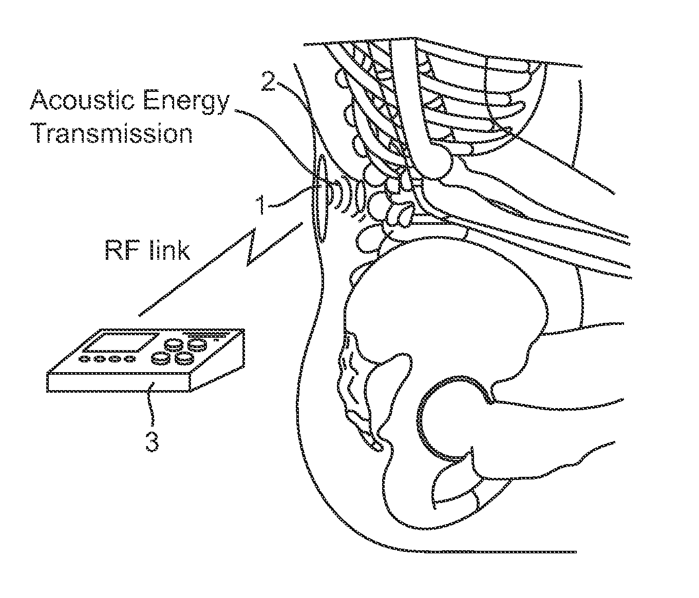
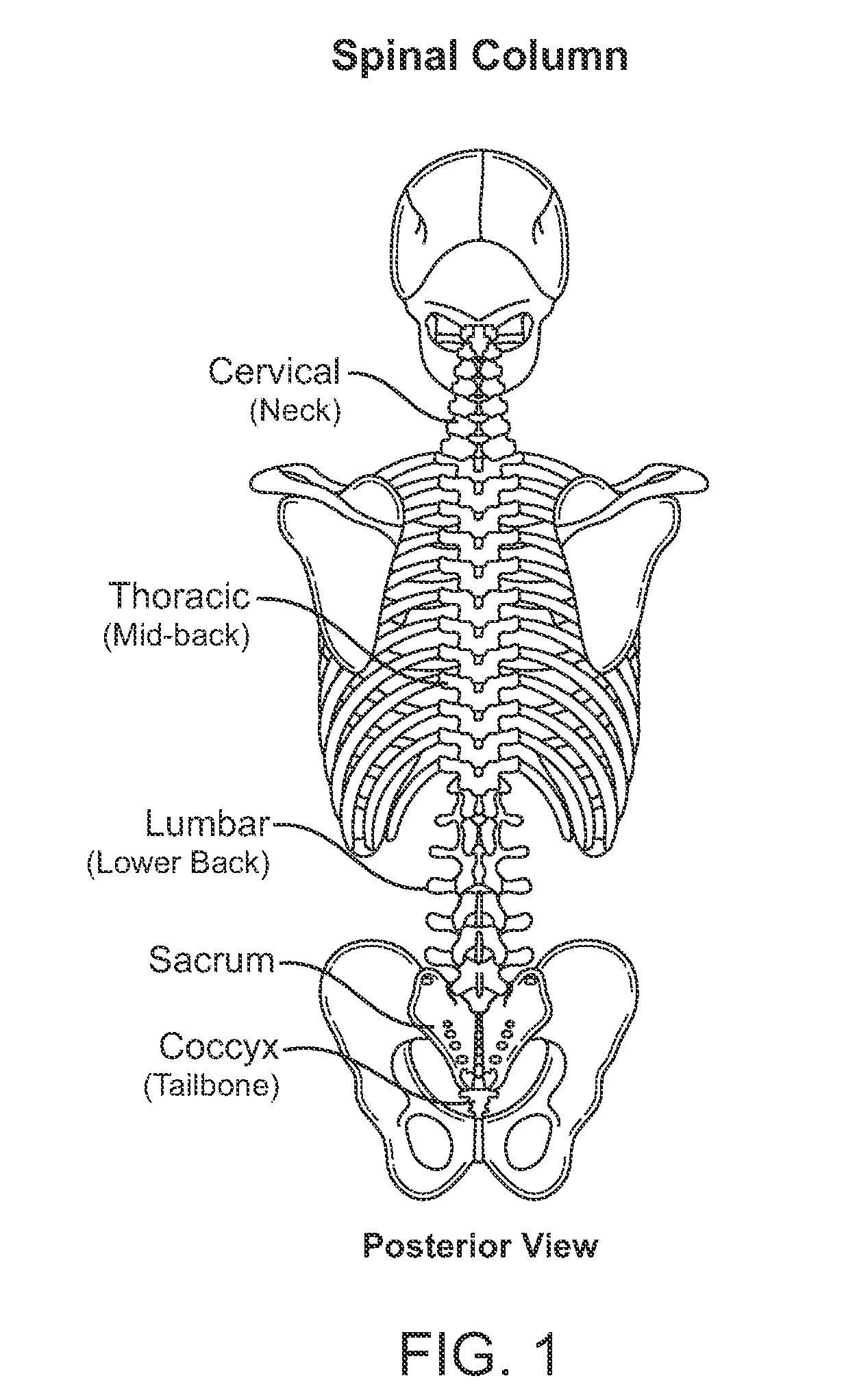
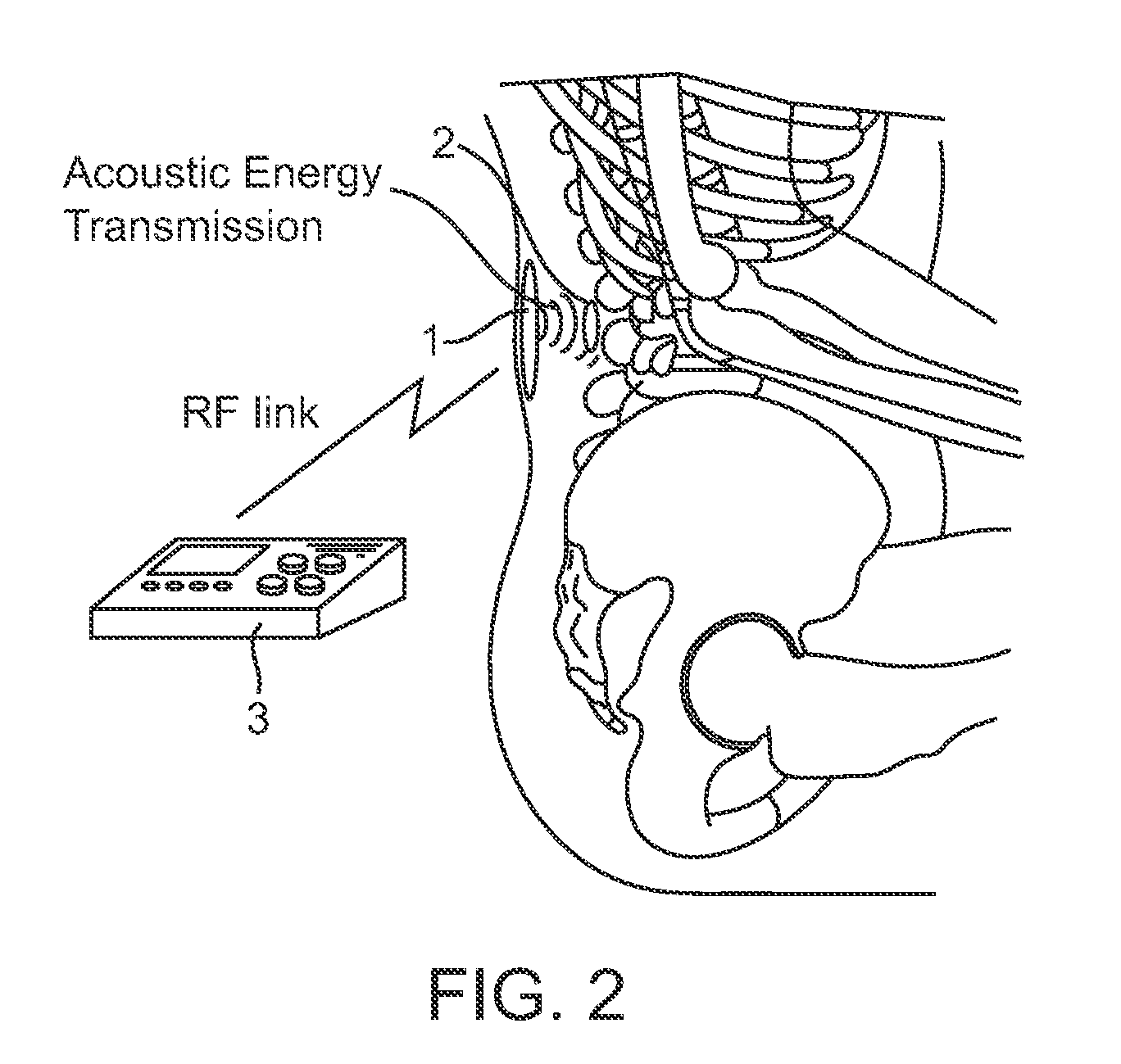
[0019]This application of leadless electrical stimulation is for spinal cord stimulation purposes, where the stimulation acts on the nerves to reduce pain. The invention is a system comprising a controller-transmitter, an implanted receiver-stimulator, a programmer to adjust therapy parameters, and stimulation electrodes, such that the stimulation electrodes would be in contact with tissue in the spine regions, in close proximity to the tissue or region to be stimulated to facilitate treatment. Systems incorporating the concepts presented have advantages over currently available devices, particularly by eliminating the requirement for electrical leads, and by providing the capability for simultaneous or sequenced stimulation of multiple sites.
[0021]In one use of the external embodiment of the controller-transmitter, the device is for pain management of recurring but not continuous pain, for example, headache pain. In the external embodiment, miniaturized receiver-stimulator devices are implanted, but the controller-transmitter unit is external to the body, possibly hand-held or worn attached to a belt or harness. The acoustic energy from the external controller-transmitter is coupled through the skin as well as any underlying tissues, to the implanted device. The external controller-transmitter is under control of the patient. Thus, when the patient begins to feel pain, the controller-transmitter unit is applied and / or switched on, and certain characteristics, for example, the level of stimulating energy and possibly the frequency or pulse duration of the stimulating waveform, is modified by the user, enabling the user to tailor the stimulation as needed to diminish the pain.

Problems solved by technology

Application of an electrical field to nerve tissue in the spine (i.e., spinal nerve roots and spinal cord bundles) is known to effectively interfere with the transmission of pain signals to the brain.
The use of these lead wires is associated with significant problems such as complications due to infection, lead failure, lead migration, and electrode / lead dislodgement.
For example, self-contained implantable microstimulators and remotely powered microstimulators have been described; however each approach suffers from some significant limitation.
A self-contained microstimulator must incorporate a battery or some other power supply; this imposes constraints on size, device lifetime, available stimulation energy, or all three.
RF energy transmission, unless the transmitting and receiving antennae are placed in close proximity, suffers from inefficiency and limited safe power transfer capabilities, limiting its usefulness in applications where recharging or stimulation must be accomplished at any significant depth (>1-2 cm) within the body, in particular where it is desired to permanently implant both the transmitter and receiver-stimulator.

Method used


Image

  • Systems and methods for implantable leadless spine stimulation
  • Systems and methods for implantable leadless spine stimulation
  • Systems and methods for implantable leadless spine stimulation

Examples


Embodiment Construction

[0028]The systems and devices described here comprise a controller-transmitter device that will deliver vibrational energy and signal information to one or more implanted receiver-stimulator device(s) that will convert the vibrational energy to electrical energy of a form that can be used to electrically stimulate nerve tissue in the spine. The vibrational energy can be applied with ultrasound as a single burst or as multiple bursts or as a continuous wave with appropriate selection of the following parameters:

[0029]

ParameterValue RangeUltrasound frequency20 kHz-10 MHzBurst Length (#cycles)3-ContinuousStimulation Pulse Duration0.1 μsec-ContinuousDuty Cycle0-100%Mechanical Index≦1.9

[0030]The controller-transmitter device would contain an ultrasound transducer or transducers of appropriate size(s) and aperture(s) to generate sufficient acoustic power to achieve the desired stimulation at the location of an implanted receiver-stimulator device. Additionally, multiple implanted receiver...


PUM


Abstract

Systems and methods are disclosed to stimulate spine tissue to treat medical conditions such as pain and spinal injury. The invention uses electrical stimulation of the spine, where vibrational energy from a source is received by an implanted device and converted to electrical energy and the converted electrical energy is used by implanted electrodes to stimulate the pre-determined brain site. The vibrational energy is generated by a controller-transmitter, which could be located either externally or implanted. The vibrational energy is received by a receiver-stimulator, which could be located in the various regions on around the spine. The implantable receiver-stimulator stimulates different locations in the spine region to provide therapeutic benefit.

Description

CROSS-REFERENCES TO RELATED APPLICATIONS[0001]The present application claims the benefit of provisional U.S. Application No. 60 / 805,315, filed Jun. 20, 2006, the full disclosure of which is incorporated herein by reference.BACKGROUND OF THE INVENTION[0002]1. Field of the Invention[0003]The systems and methods of this invention relate to direct electrical stimulation of nerve tissue in the spinal cord or spinal column for treatment of pain due to a variety of medical conditions. Specifically, the present invention relates to methods and apparatus for applying such stimulation without the use of conventional lead / electrode systems.[0004]2. Description of the Background Art[0005]Electrical stimulation of spinal nerve roots, the spinal cord, and / or other nerve bundles in the region of the spine, for the purpose of chronic pain management, has been actively practiced since the 1960s. Application of an electrical field to nerve tissue in the spine (i.e., spinal nerve roots and spinal cord...

Claims


Application Information

Patent Timeline
Patent Type & Authority Patents(United States)
IPC IPC(8): A61N1/372
CPCA61N1/37217A61N1/36071A61N1/37288A61N1/3756
Inventor COWAN, MARK W.RILEY, RICHARD E.BRISKEN, AXEL F.ECHT, DEBRA S.
Owner EBR SYST
Learn More