Hinge structure for self-closing doors

a self-closing, hinge technology, applied in the direction of wing openers, multi-purpose tools, constructions, etc., can solve the problems of inability to adjust, complex assembly and maintenance, and poor versatility of the hinge structure, so as to achieve easy and convenient maintenance, simple construction, and high performance.

Active Publication Date: 2011-03-08
GOSIO DIANORA
View PDF11 Cites 38 Cited by
  • Summary
  • Abstract
  • Description
  • Claims
  • Application Information

AI Technical Summary

Benefits of technology

[0014]The main object of this invention is to obviate the above drawbacks, by providing an hinge structure allowing for easy and convenient maintenance, that has high performance, simple construction and low cost properties.
[0015]One object of the invention is to provide a hinge structure that allows the automatic closing of the door from the open position.
[0016]A particular object is to provide a hinge structure that allows the controlled motion of the door with which it is connected.

Problems solved by technology

These prior art hinge structures suffer from certain well-recognized drawbacks.
A first drawback is their bulky size, heavy weight and high cost, caused by their being formed of many different parts, which further complicate their assembly and maintenance.
Furthermore, they exhibit poor versatility and have to be replaced or anyway adjusted as the door or frame on which they are mounted changes.
Also, these prior art hinge structures do not assure controlled motion of the door during opening and closing thereof.
This problem is particularly felt with glass doors, whose closing and opening movements must be smooth, to avoid irreversible damages to the door itself.
However, the behavior of these prior art structures is highly affected by the mass of the door on which they are mounted.
Furthermore, in operation, these prior art hinge structures are subjected to variations in their closing position, which leads to inconveniences and higher maintenance costs.
Moreover, the known structures do not allow the automatic closing movement of the door upon the opening.

Method used


Image

  • Hinge structure for self-closing doors
  • Hinge structure for self-closing doors
  • Hinge structure for self-closing doors

Examples


second embodiment

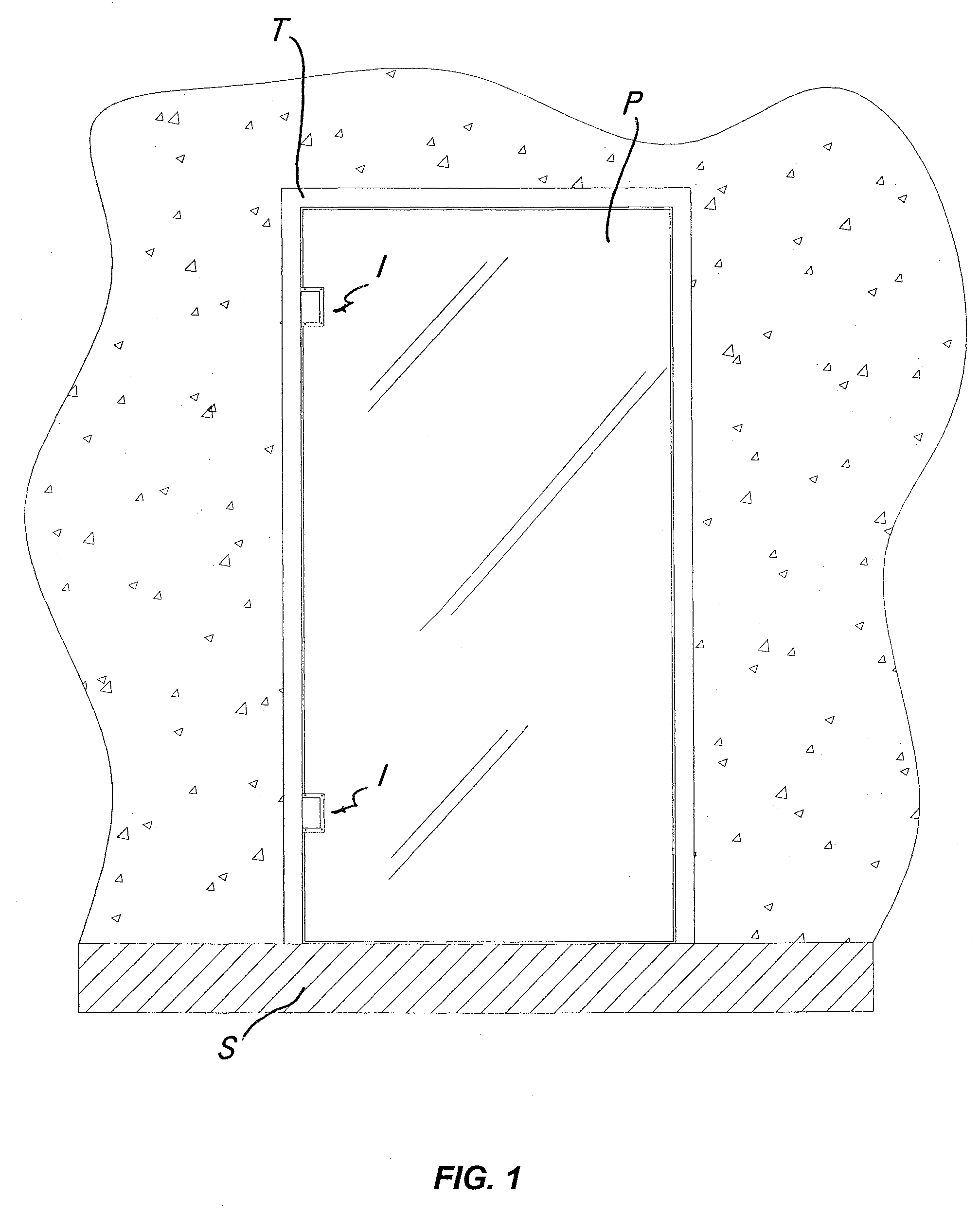
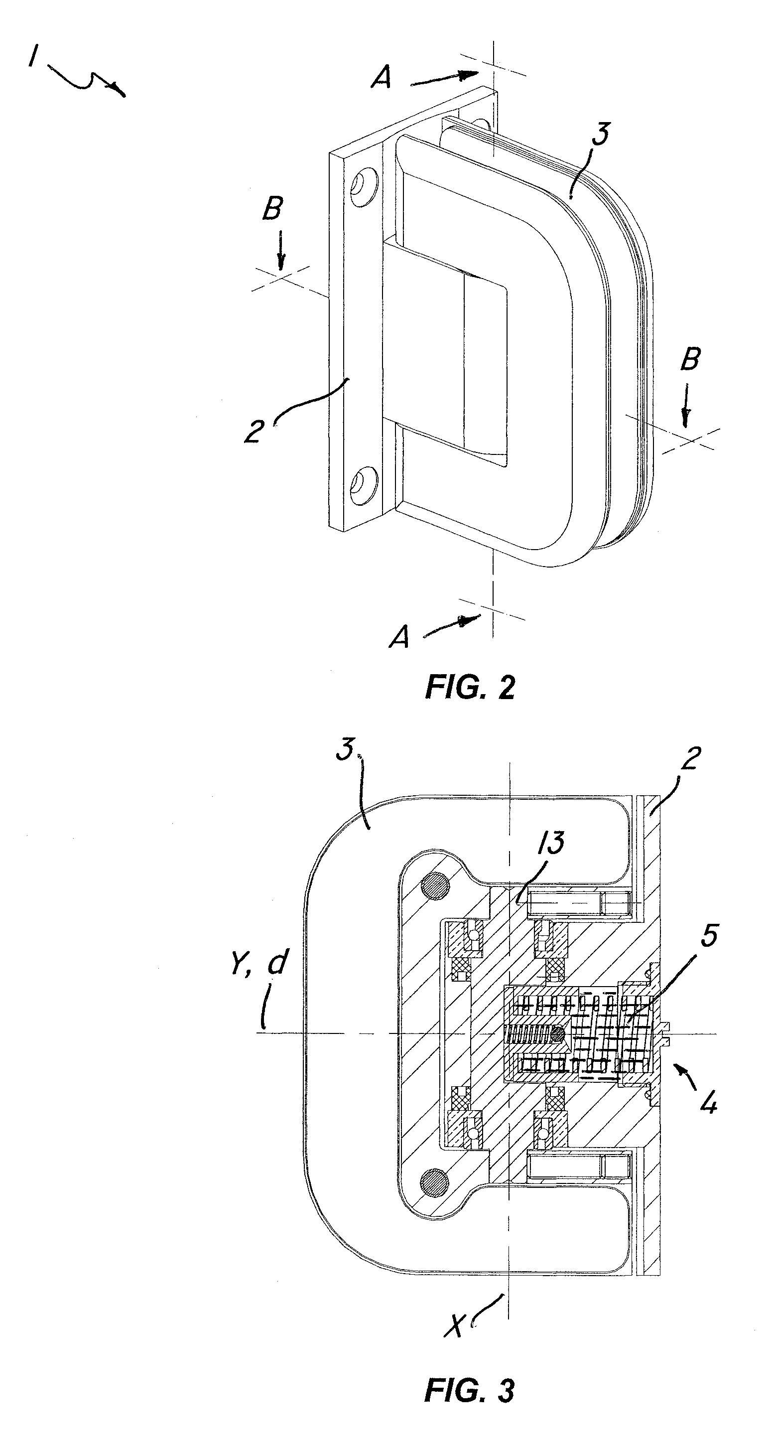
[0090]FIGS. 11 to 24 show without limitation the hinge structure of the invention, generally designated by numeral 1′. The latter essentially comprises a stationary element 2 and a movable element 3 to be fixed to a door P by the two half shells 42, 42′. The stationary element 2 is designed to be fixed to a stationary support S, such as a wall or a floor, through the skirting 43, as shown in FIG. 24.

[0091]This second embodiment differs from the first embodiment in that, while the closing means 4 are held in a single first operating chamber 6, the hydraulic damping means 5 are held both in this first operating chamber 6 and in a second operating chamber 44, which is in fluid connection therewith. As shown in FIG. 14, both the first operating chamber 6 and the second operating chamber 44 are wholly contained in the box-like housing defined by the stationary element 2.

[0092]This configuration allows controlled movement of very heavy doors P and / or gates. This result is achieved thanks ...

first embodiment

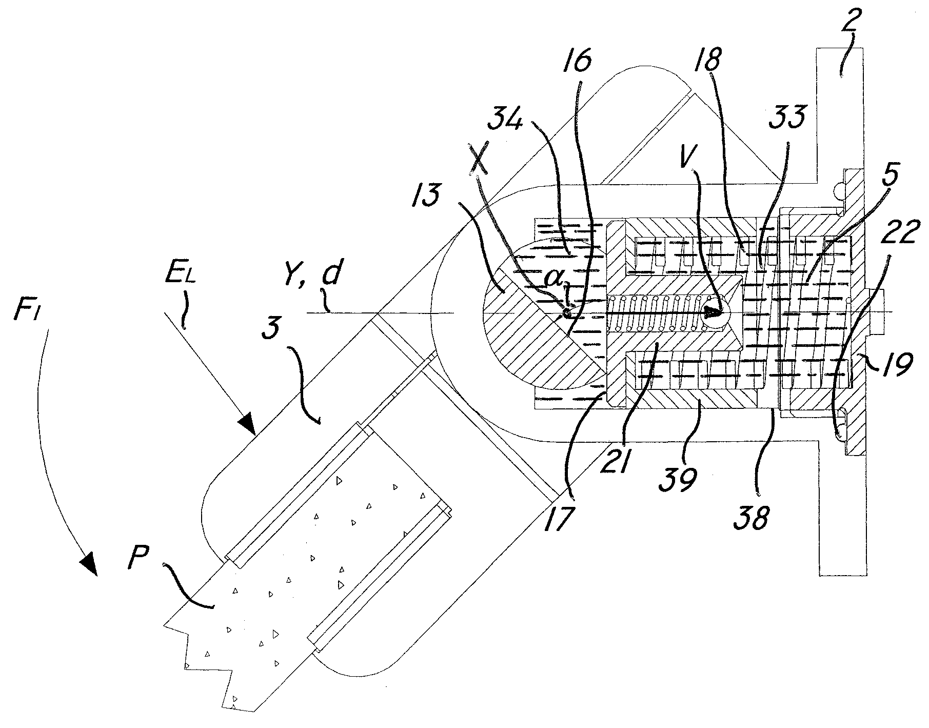
[0097]In this embodiment, both the first cam element 11 and the second cam element 45 are formed by specially shaping the central portion 14 of the pin 13. The first cam element 11, like in the first embodiment, comprises a first substantially flat surface 16, parallel to the axis X and abutting against the front face 17 of the first plunger element 12. The second cam element 45, placed above the first, is substantially defined by a wall 48 having a pair of second substantially flat surfaces 49, 49′, parallel to the axis X and substantially perpendicular to the first surface 16.

[0098]The wall 48, with its surfaces 49, 49′ abuts against the front face 50 of the second plunger element 46. For this purpose, as better shown in FIG. 16, the cylindrical receptacle 24 is designed to communicate both with the first operating chamber 6 and with the second 44, at the area of contact between the first cam element 11 and the first plunger element 12 and at the area of contact between the second...


PUM


Abstract

A hinge structure (1) for self-closing doors or the like comprises a first stationary element (2) attachable to the frame (T) of a door (P), a first movable element (3) securable to the door (P) and pivotally mounted to the first stationary element (2) for rotating about a longitudinal axis (X) between an open door position and a closed door position. The structure (1) further comprises closing means (4) acting on the first movable element (3) for automatically returning the door (P) to the closed position during opening, hydraulic damping means (5) operating on the first movable element (3) to oppose and damp the movement produced by the closing means (4). The closing means (4) and the hydraulic damping means (5) are housed within a first operating chamber (6) locate internally of the first stationary element (2). An assembly incorporates such hinge structure.

Description

FIELD OF THE INVENTION[0001]The present invention finds application in the field of hinges and suspension hardware for doors or the like, and particularly relates to hinge structure for self-closing doors.[0002]The hinge structure of the invention can assure self-closing of any kind of door, window or shutter, whether horizontally or vertically oriented, particularly of glass doors.[0003]The invention further relates to an assembly incorporating such hinge structure.BACKGROUND OF THE INVENTION[0004]Hinge structure for self-closing doors or the like, particularly glass doors or the like are known in the art.[0005]These prior art hinge structures comprise, as is known, a stationary element to be fixed to the frame of a door, a first movable element to be attached to the door and pivotally mounted to the stationary element for rotating about a longitudinal axis between an open door position and a closed door position.[0006]These prior art hinge structures further comprise means for aut...

Claims


Application Information

Patent Timeline
Patent Type & Authority Patents(United States)
IPC IPC(8): E05D5/02
CPCE05D5/0246E05F3/20E05F3/104E05Y2800/672Y10T16/554Y10T16/534Y10T16/2771Y10T16/5383E05Y2900/132
Inventor BACCHETTI, LUCIANO
Owner GOSIO DIANORA
Why Eureka
Try Eureka