Current bypass for distributed power harvesting systems using DC power sources
What is Al technical title?
Al technical title is built by PatSnap Al team. It summarizes the technical point description of the patent document.
a technology of dc power source and current bypass, which is applied in the direction of electric variable regulation, process and machine control, instruments, etc., can solve the problems of affecting the operation of the entire installation, and stopping the flow of current in the entire series connection
Active Publication Date: 2011-03-08
SOLAREDGE TECH LTD
View PDF111 Cites 181 Cited by
Summary
Abstract
Description
Claims
Application Information
AI Technical Summary
This helps you quickly interpret patents by identifying the three key elements:
Problems solved by technology
Method used
Benefits of technology
[0012]According to aspects of the invention, there is provided a current bypass in converters used in distributed DC power sources system, such as, e.g., photovoltaic panels installation, to increase the overall reliability of the power harvesting circuit in the case of component failure, and allow other series-connected circuits to keep on functioning as normal.
[0017]According to further aspects of the invention, a method for providing one or more current bypass routes in a series connection of power cells is provided, the method comprising: coupling each of the power cells to a corresponding converter; coupling output leads of the converters in series; and providing a plurality of current bypass routes in each of the converters, wherein the current bypass routes provide routes between the output leads of each of the converters from a negative output lead to a positive output lead and prevent current flow from the positive output lead to the negative output lead. The method may further comprise: providing a buck portion in each of the converters; providing a boost portion in each of the converters; and selectively activating either the buck portion or the boost portion or both using a controller included in each of the converters, wherein at least one of the current bypass routes is provided in the buck portion and at least one of the current bypass routes is provided in the boost portion. The method may further comprise providing overall bypass routes in each of the converters, the overall bypass route passing outside the buck portion and the boost portion. The method may further comprise: providing redundancy by forming some of the current bypass routes parallel to portions of other current bypass routes.
Problems solved by technology
Malfunction of one may disturb the operation of the entire installation.
For example, in series connections an open circuit malfunction in one converter may stop the flow of current in the entire series connection.
Method used
Image
Click on the blue label to locate the original text in one second.
Reading with bidirectional positioning of images and text.
Examples
Embodiment Construction
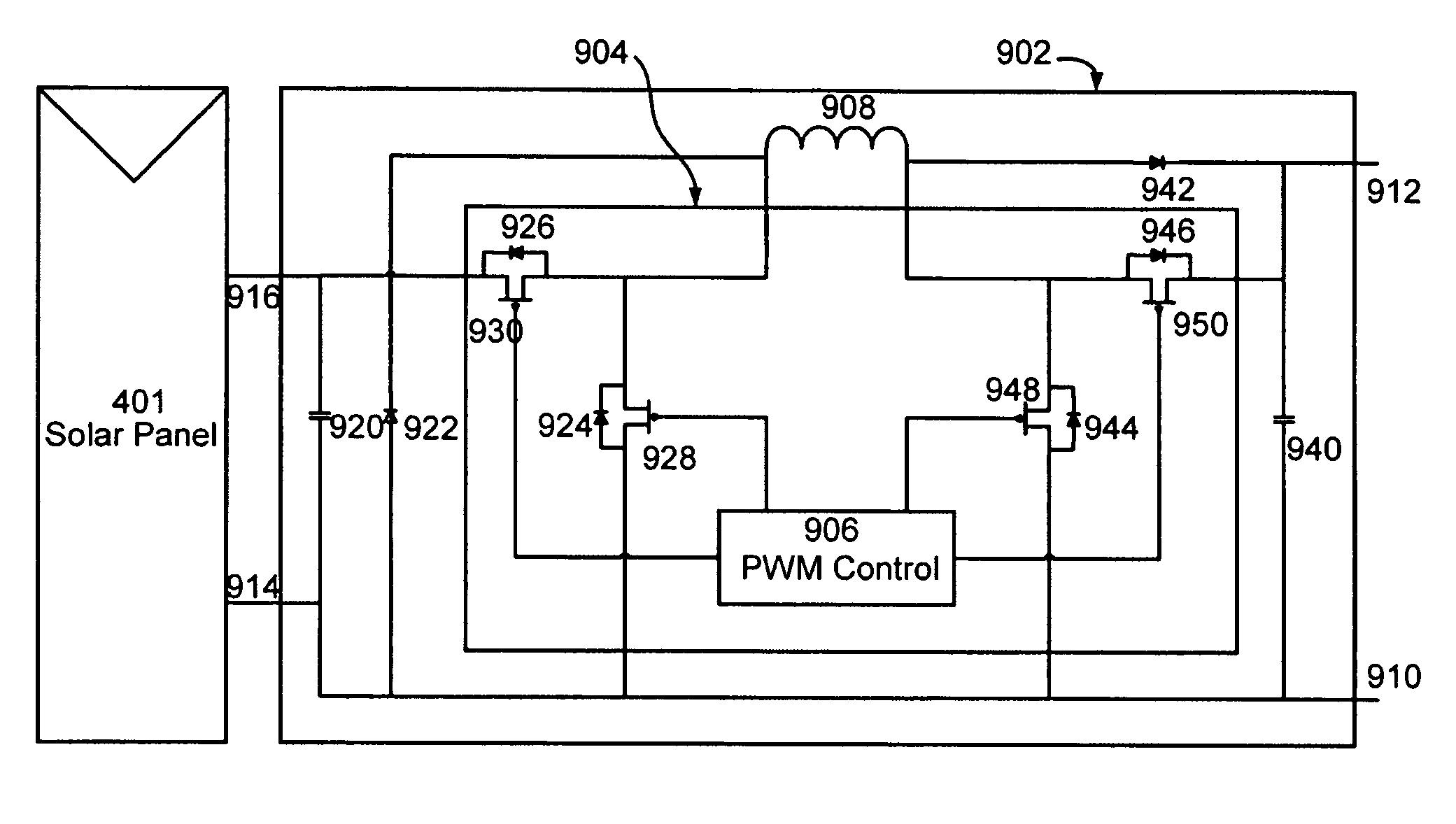
[0035]Aspects of the present invention provide a DC-to-DC converter that includes both current bypass paths and current blocking paths. The current bypass paths are for preventing the converter to open a series connected circuit. The current blocking paths are for preventing the converter from shorting a parallel connected circuit.
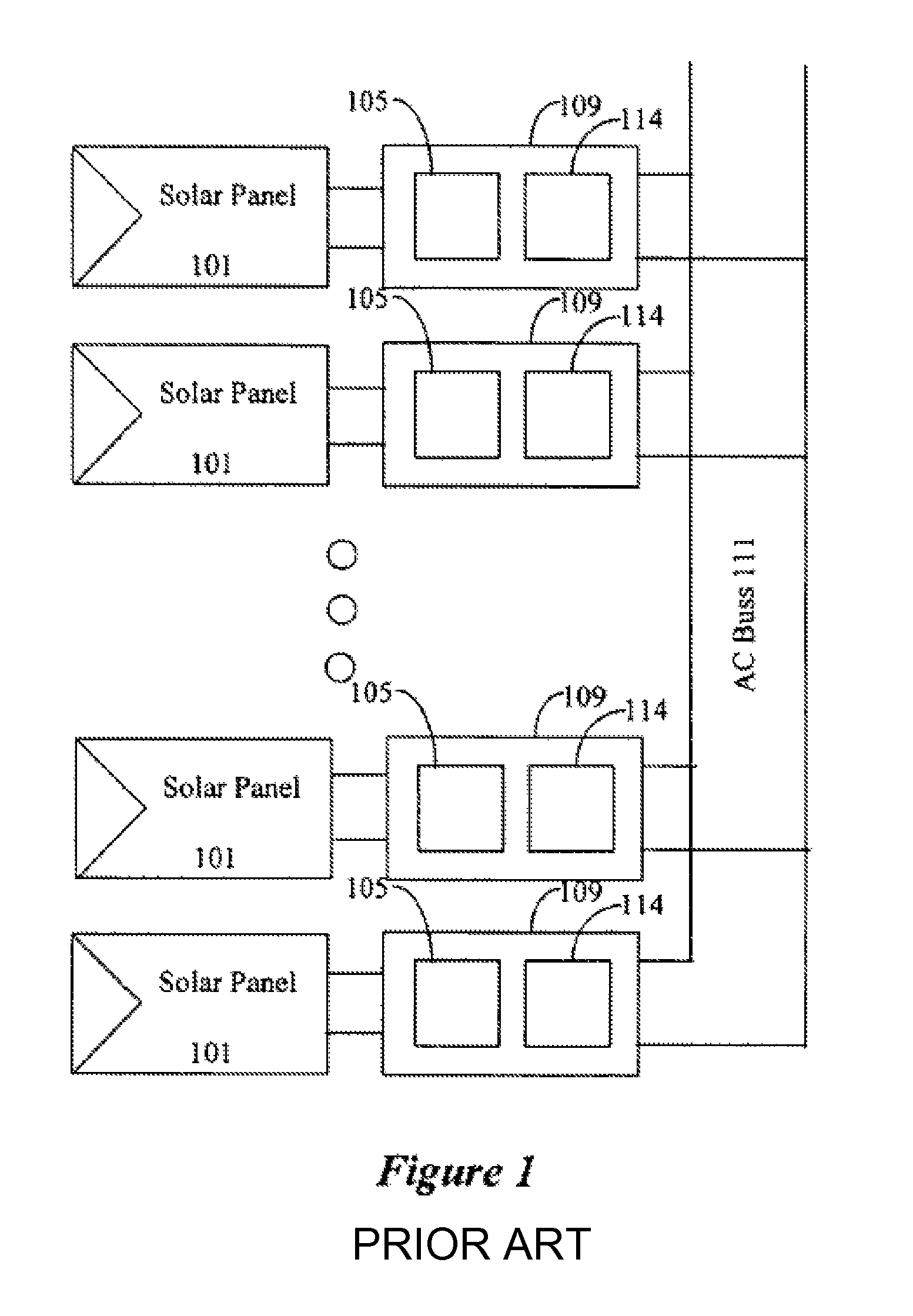
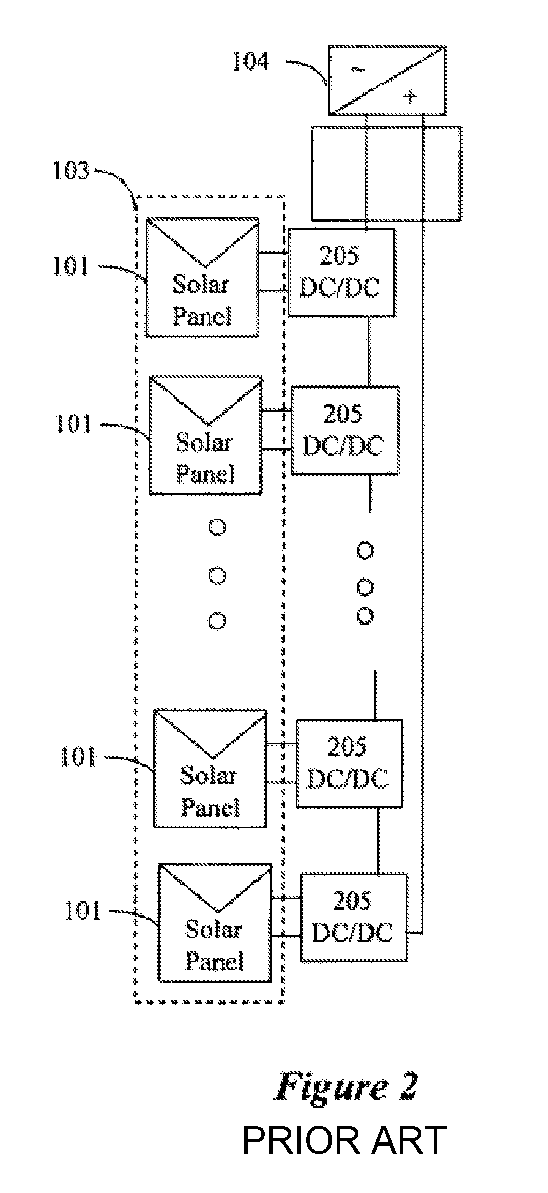
[0036]Aspects of the present invention provide a current bypass mechanism for the electrical power converters that are connected together in series in a distributed power harvesting system. According to aspects of the invention, each converter has one or more current bypass paths on failure. As a result, upon failure of one of the electrical power converters, current still flows through the failed electrical power converter and does not cut current from the entire series connection of the power sources. While described in the context of solar power technology, the reliability enhancing aspects of the present invention may be used in converters used in any ...
PUM
Abstract
A converter circuit providing multiple current bypass routes between the output leads to provide reliability in a series connection of several converters. If the converter malfunctions due to component failure, the current bypass routes provide a path for the current that views the malfunctioning converter as substantially a short. Diodes prevent backflow into the power source connected to the converter. Redundancy is provided in the bypass portions of the converter circuit that provides alternate parallel paths in case a defective component in one of the paths opens the circuit along that path. In one example, the converter is implemented as a buck plus boost converter where either the buck or the boost portion or both are operative responsive to a controller controlling the switches of both portions. Most of the converter circuit may be implemented in an integrated circuit.
Description
CROSS-REFERENCE TO RELATED APPLICATIONS[0001]This Application claims priority to U.S. Provisional Patent Applications, Ser. No. 60 / 868,851, filed Dec. 6, 2006, and titled “Distributed Solar Array Monitoring, Management and Maintenance,” Ser. No. 60 / 868,893, filed Dec. 6, 2006, and titled “Distributed Power Harvesting System for Distributed Power Sources,” 60 / 868,962, filed Dec. 7, 2006, and titled “System, Method and Apparatus for Chemically Independent Battery,” Ser. No. 60 / 908,095, filed Mar. 26, 2007, and titled “System and Method for Power Harvesting from Distributed Power Sources,” and Ser. No. 60 / 916,815, filed May 9, 2007, and titled “Harvesting Power From Direct Current Power Sources,” the entire content of which is incorporated herein by reference. Further, this Application is related to ordinary U.S. Patent Applications titled “Distributed Power Harvesting Systems Using DC Power Sources,”“Monitoring of Distributed Power Harvesting Systems Using DC Power Sources,”“Removable...
Claims
Application Information
Patent Timeline
Application Date:The date an application was filed.
Publication Date:The date a patent or application was officially published.
First Publication Date:The earliest publication date of a patent with the same application number.
Issue Date:Publication date of the patent grant document.
PCT Entry Date:The Entry date of PCT National Phase.
Estimated Expiry Date:The statutory expiry date of a patent right according to the Patent Law, and it is the longest term of protection that the patent right can achieve without the termination of the patent right due to other reasons(Term extension factor has been taken into account ).
Invalid Date:Actual expiry date is based on effective date or publication date of legal transaction data of invalid patent.