Variable rotor blade for gas turbine engine

a gas turbine engine and variable technology, applied in the field of variable rotor blades and variable rotor blade actuation mechanisms, can solve the problems of impracticality of variable camber compressor sections, limited attempts at variable pitch compressor sections,

Inactive Publication Date: 2011-03-08
RAYTHEON TECH CORP
View PDF21 Cites 30 Cited by
  • Summary
  • Abstract
  • Description
  • Claims
  • Application Information

AI Technical Summary

Problems solved by technology

Thus, attempts at variable pitch compressor sections have typically been limited to variable stator vanes due to the complexity necessary for actuating a rotating blade, and to the heavy centrifugal loads placed on the blades during engine operation.
However, due to the complexity of varying the shape of a body that must remain rigid under high stress while rotating, variable camber compressor sections have typically been impractical.

Method used


Image

  • Variable rotor blade for gas turbine engine
  • Variable rotor blade for gas turbine engine
  • Variable rotor blade for gas turbine engine

Examples


Embodiment Construction

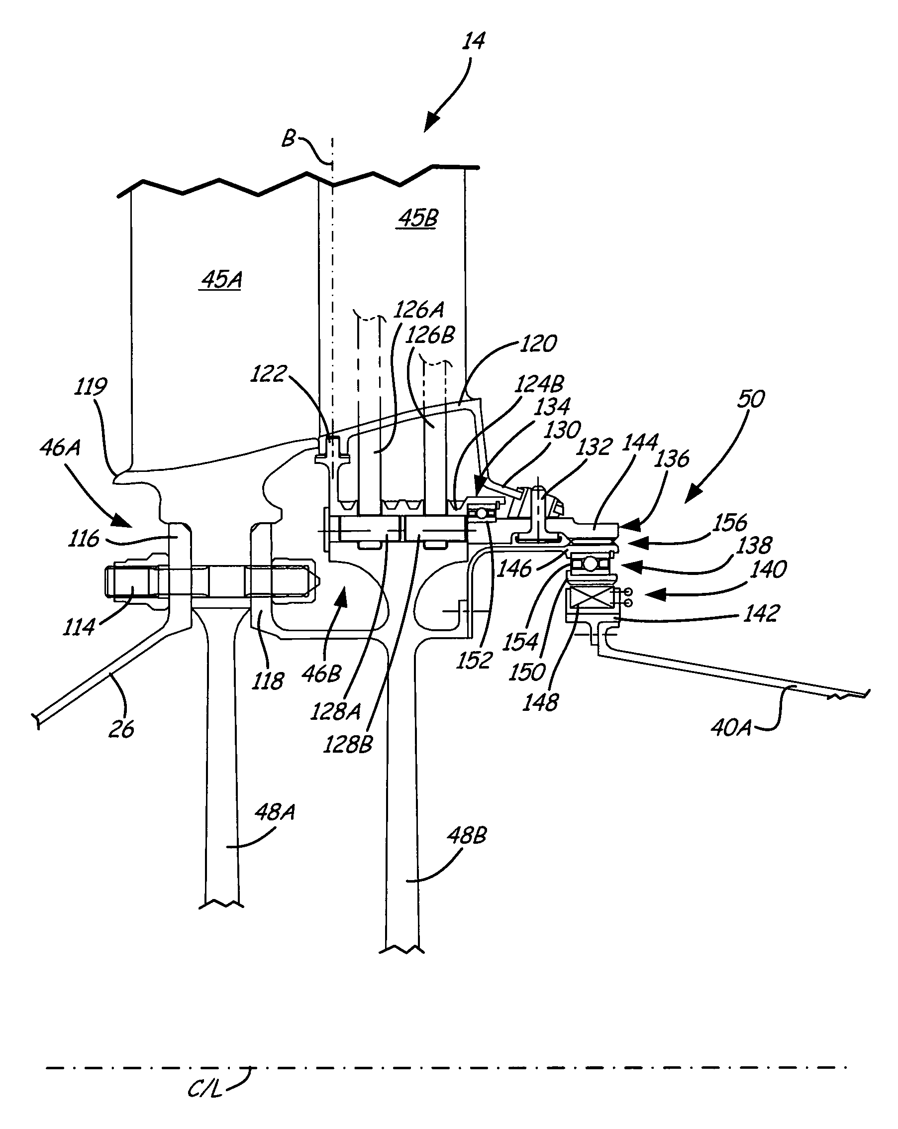
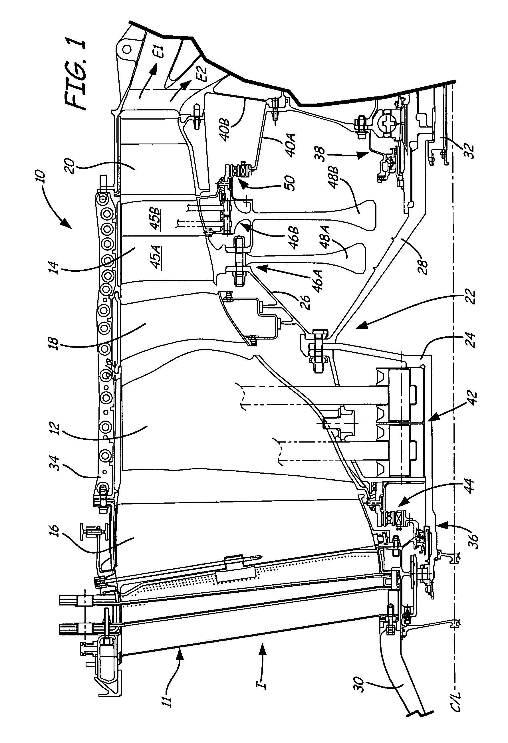
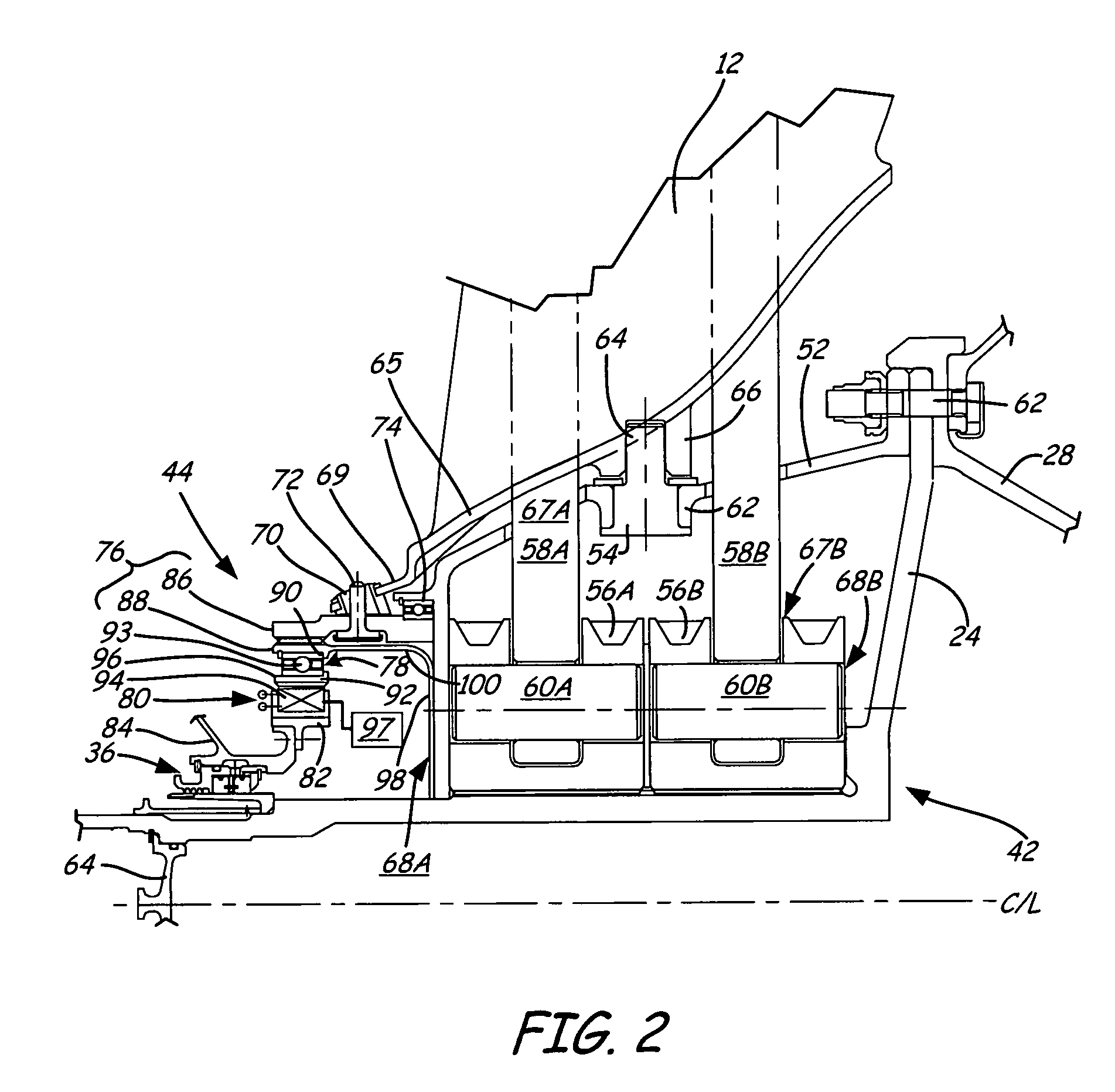
[0013]FIG. 1 shows a cross sectional view of two-stage turbofan engine 10. Engine 10 includes two-stage fan section 11, which includes variable pitch first-stage blade 12 and variable camber second-stage blade 14 inter-disposed between inlet guide vane 16, intermediate guide vane 18 and exit guide vane 20. Two-stage fan section 11 receives inlet air I, and produces both propulsive thrust output at exit E1 and compressed air used for combustion at exit E2. First-stage blade 12 and second-stage blade 14 are joined at their inner diameter ends to fan shaft 22, which is comprised of first-stage section 24, second-stage section 26 and conical support 28. Fan shaft 22 is connected with turbine shaft 32 at its aft end. Turbine shaft 32 is connected with a turbine at its aft end such that fan shaft 22 is driven to rotate about engine centerline CL. Guide vanes 16, 18 and 20 are fixedly attached to fan case 34 at their outer diameter ends. Inlet guide vane 16 is supported at its inner diamet...


PUM


Abstract

A variable rotor blade mechanism for use in a gas turbine engine comprises a blade rotor, a blade, a harmonic drive system, a stepper motor and a bracket. The blade rotor rotates absolutely about an axial engine centerline during operation of the gas turbine engine. The blade extends radially from the blade rotor and is configured to be adjustable by rotation about a radial axis. The harmonic drive system is mounted to the blade rotor and connected to the blade to rotate the blade about the radial axis. The stepper motor drives the harmonic drive with relative rotational input with respect to the absolute rotation of the blade rotor. The bracket is disposed about the engine centerline and supports the stepper motor stationary with respect to the rotation of blade rotor such that the relative rotational input to the stepper motor is generated.

Description

BACKGROUND OF THE INVENTION[0001]The present invention is related to gas turbine engines, and in particular to variable rotor blades and variable rotor blade actuation mechanisms.[0002]Gas turbine engines operate by combusting fuel in compressed air to create heated gases with increased pressure and density. The heated gases are ultimately forced through an exhaust nozzle, which is used to step up the velocity of the exiting gases and in-turn produce thrust for driving an aircraft. In turbofan engines the heated gases are used to drive a turbine for rotating a fan to produce thrust, and to drive a turbine for driving a compressor that provides the compressed air used during combustion. The compressor section of a gas turbine engine typically comprises a series of rotor blade and stator vane stages. At each stage, rotating blades push air past the stationary vanes. Each rotor / stator stage increases the pressure and density of the air. Stators convert the kinetic energy of the air int...

Claims


Application Information

Patent Timeline
Patent Type & Authority Patents(United States)
IPC IPC(8): B64C11/44
CPCF01D5/148F01D5/30F01D7/02F04D29/362Y02T50/673F05D2260/74F05D2260/76F05D2260/79F05D2260/71Y10S416/05F04D29/323F05D2220/36Y02T50/60
Inventor SUCIU, GABRIEL L.NORDEEN, CRAIG A.
Owner RAYTHEON TECH CORP
Why Eureka
Try Eureka