Supercharge Your Innovation With Domain-Expert AI Agents!

Manufacturing method for vibrator

a manufacturing method and vibrator technology, applied in the manufacture of cables/conductor devices, electrical equipment, decorative arts, etc., can solve the problems of poor operation efficiency, more complicated processes, misalignment between, etc., and achieve the effect of simple processes, satisfactory pattern accuracy, and no extension of exposure tim

Inactive Publication Date: 2011-03-08
CITIZEN WATCH CO LTD
View PDF7 Cites 0 Cited by
  • Summary
  • Abstract
  • Description
  • Claims
  • Application Information

AI Technical Summary

Benefits of technology

The present invention provides a method for manufacturing a vibrator with groove portions that are simple and have high accuracy. The method involves forming a metal film on a substrate, patterning the film to remove unnecessary parts, etching away exposed parts of the substrate, patterning the film again to remove any remaining parts, and etching the substrate to form the groove portion. This method allows for the formation of groove portions without complicating the process or reducing pattern accuracy.

Problems solved by technology

In the manufacturing method described above, however, the photoresist layer 7 must be formed and exfoliated twice, so that more complicated processes are required than in a manufacturing method for an ordinary tuning fork-type crystal vibrator without any grooves in its cross section, and the operating efficiency is poor.
Accordingly, there is a problem that misalignment is caused between the primarily formed metal films (Au film 5 and Cr film 3) and the new photoresist film.
However, the alternative prior art manufacturing method described above has the following problems.
There is a problem that the degenerated-surface layer of the photoresist layer 7 cannot be developed if an attempt is made to extend or even decouple the exposure time in order to compensate for the reduction of the exposure sensitivity of the degenerated-surface layer.
If the exposure is prolonged, moreover, the exposure time is too long for the photoresist at an undegenerated region, so that the dimensional accuracy of patterns worsens inevitably.
If an attempt is made to remove the degenerated-surface layer of the photoresist layer by an alkaline solution, such as a developer, before the exposure, moreover, the degenerated-surface layer is hardly dissoluble in the alkaline solution, so that it is difficult to remove the degenerated-surface layer thoroughly.
According to the method in which the degenerated-surface layer is removed by dry etching using oxygen plasma, furthermore, the processes are complicated, and besides, the photoresist layer is unexpectedly exposed to ultraviolet rays generated from the oxygen plasma, so that the pattern accuracy of the groove portions 9 worsens.

Method used


Image

  • Manufacturing method for vibrator
  • Manufacturing method for vibrator
  • Manufacturing method for vibrator

Examples


Embodiment Construction

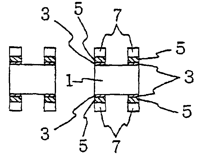
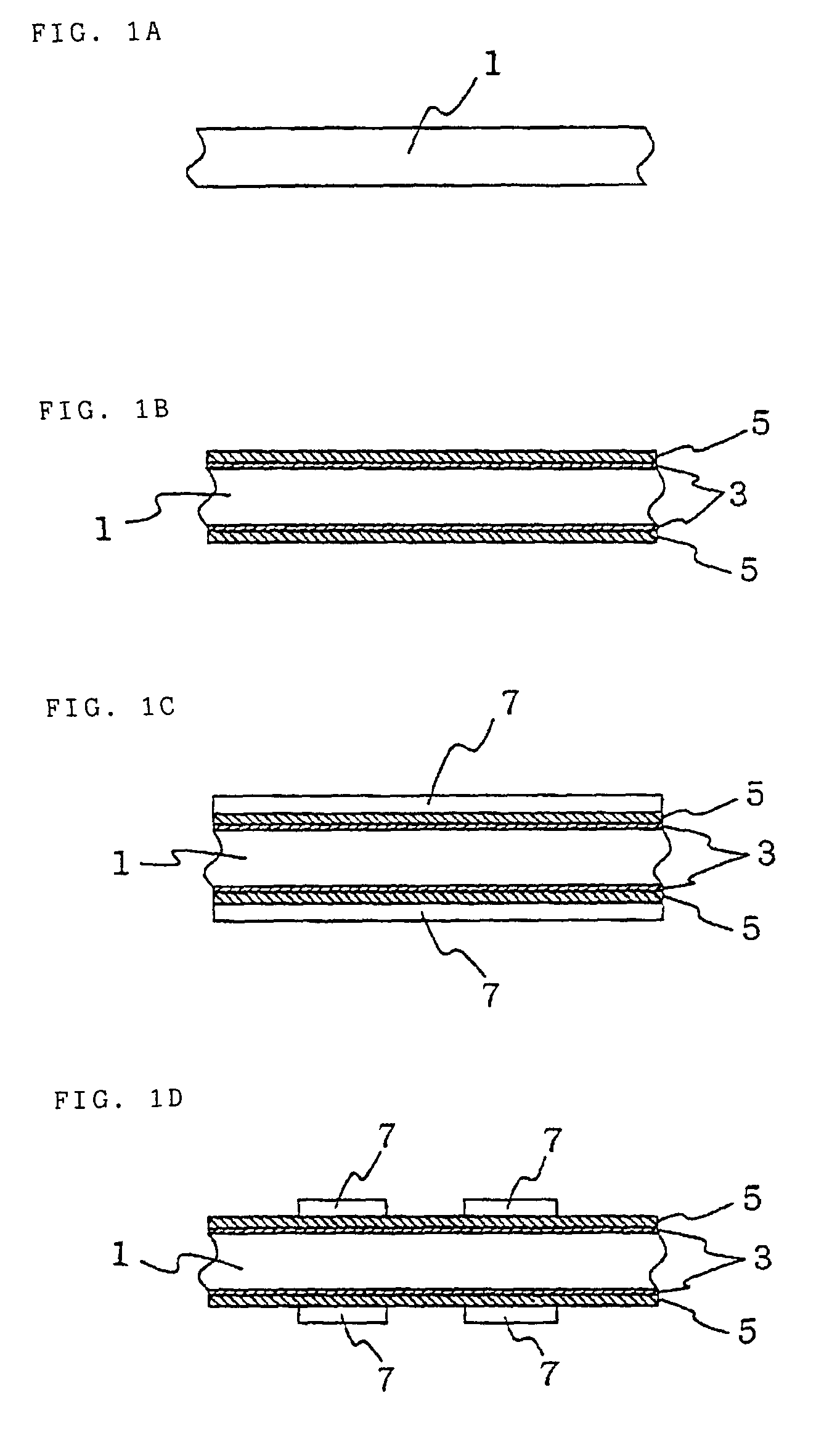
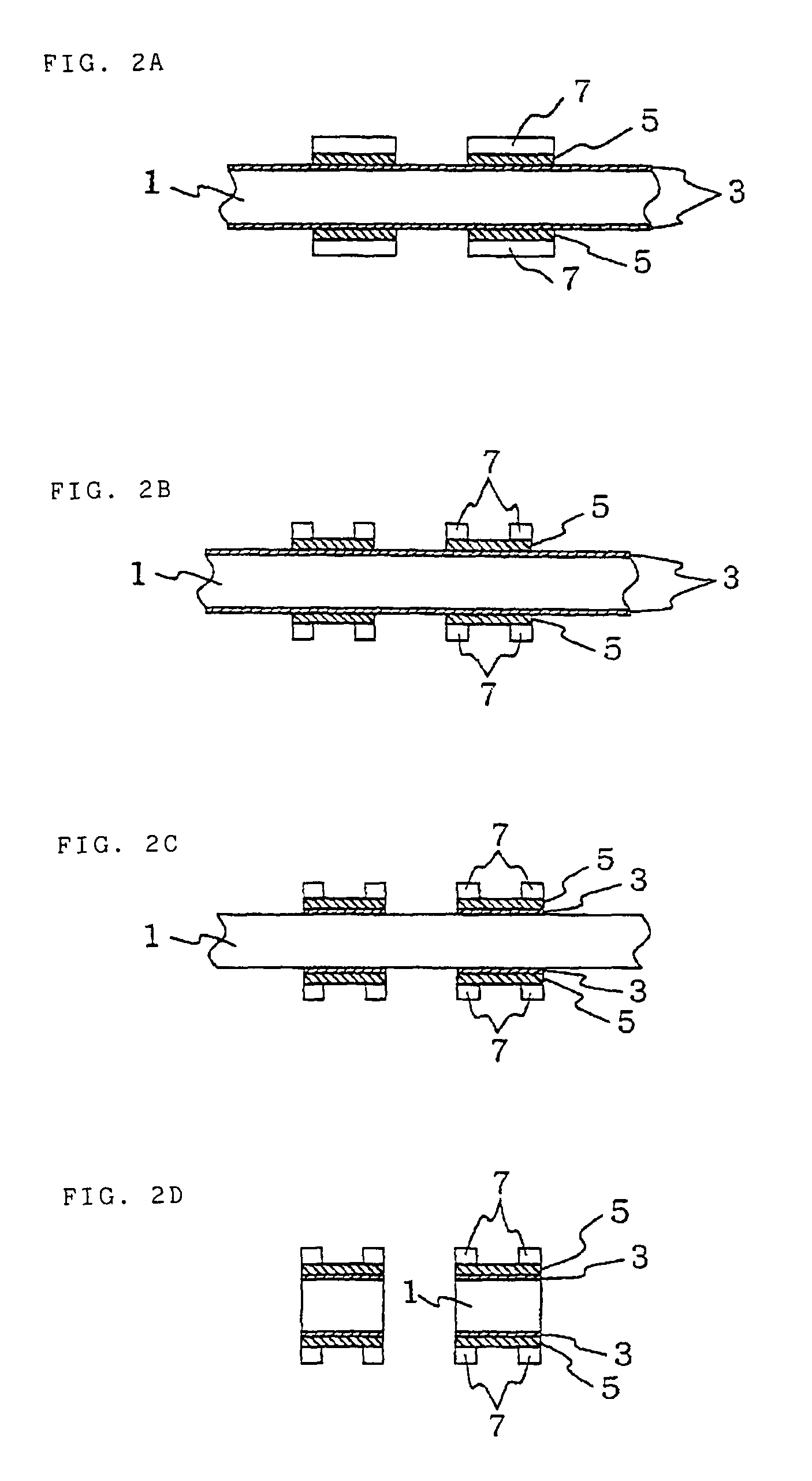
[0040]FIGS. 1A to 3D are views individually showing manufacturing processes for a vibrator according to the present invention.

[0041]First, a crystal substrate 1 is worked into a plate-like structure (FIG. 1A). Then, a Cr film 3 of about 500 Å thickness is formed as a metal film for an underlayer on the obverse and reverse surfaces of the crystal substrate 1 by vapor deposition or sputtering. Subsequently, an Au film 5 of about 1,000 Å thickness is formed as a metal film for a surface layer on the underlayer (FIG. 1B). The Cr film 3 functions as an intermediate layer that improves the adhesion between Au film 5 and the crystal substrate 1. Further, the Au film 5 functions as an anticorrosive film that resists a liquid mixture of hydrofluoric acid and an ammonium fluoride solution used afterward in etching crystal.

[0042]Then, a photoresist is applied to the surface of the Au film 5 and dried to form a photoresist layer 7 (FIG. 1C). For example, OFPR (trademark), a positive photoresist...


PUM

PropertyMeasurementUnit
piezoelectricaaaaaaaaaa
shapeaaaaaaaaaa
sizesaaaaaaaaaa

Abstract

After an external shape of a photoresist layer is patterned with use of a Cr film as an underlayer, i.e., a metal film to serve as an anticorrosive film that resists crystal etching, and an Au film as a surface layer, the Au film is etched. After groove portions are then patterned, the Cr film is etched. Since no degenerated-surface layer cannot be formed on the photoresist layer with an etchant for the Au film, the groove portions can be patterned without any degenerated-surface layer according to this method, so that high-accuracy groove portions can be formed.

Description

TECHNICAL FIELD[0001]The present invention relates to a manufacturing method for a vibrator formed of a vibrating piece of rock crystal or the like.BACKGROUND ART[0002]In recent years, vibrators for use as time standards for electronic devices have started to be expected so that their vibrators are of small sizes and have a small CI-value (crystal impedance or equivalent series resistance). Conventionally, known vibrators that meet this requirement, e.g., tuning fork-type crystal vibrators, include one that is constructed in the manner shown in FIGS. 7A and 7B (see Japanese Patent Application Laid-Open No. 2002-76806, for example).[0003]The tuning fork-type crystal vibrator described in the above patent document has two vibrating tines 13 that constitute a tuning fork, and groove portions 9 or slots are formed on the respective obverse and reverse surfaces of the tines 13. As shown in FIG. 7B, each tine 13 has a substantially H-shaped cross section. Drive electrodes are formed on th...

Claims


Application Information

Patent Timeline
Patent Type & Authority Patents(United States)
IPC IPC(8): B44C1/22C03C15/00C23F1/00C03C25/68
CPCH03H3/04H03H9/215H03H2003/0492
Inventor YAMAMOTO, IZUMIIKEDA, TOMOO
Owner CITIZEN WATCH CO LTD
Features
  • R&D
  • Intellectual Property
  • Life Sciences
  • Materials
  • Tech Scout
  • Unparalleled Data Quality
  • Higher Quality Content
  • 60% Fewer Hallucinations
Learn More